Suppression of four-wave mixing in ultra dense WDM optical communication systems through optical fibre dispersion map design

a technology of optical communication and dispersion map, which is applied in the direction of electromagnetic transmission, multi-communication, wavelength-division multiplex system, etc., can solve the problems of reducing transmission quality and the inability to provide the optimal net system dispersion through the use of such a dispersion map

Inactive Publication Date: 2008-01-15
RPX CLEARINGHOUSE
View PDF6 Cites 2 Cited by
  • Summary
  • Abstract
  • Description
  • Claims
  • Application Information

AI Technical Summary

Benefits of technology

[0020]As the invention only requires the use of dispersion compensating modules (some realizations of which are currently commercially available and some being in development), an obvious advantage of the invention is that the cost of implementing such a scheme should not make much difference to the overall system cost. Therefore this invention is likely to be very important to the high capacity transport market.

Problems solved by technology

It has been discovered that the exact distribution of fibre dispersion along the optical link (the ‘dispersion map’) strongly influences the degree of four-wave mixing, and hence the degradation in transmission quality.
It should be noted that the use of such a dispersion map may not provide the optimum net system dispersion.

Method used


Image

  • Suppression of four-wave mixing in ultra dense WDM optical communication systems through optical fibre dispersion map design
  • Suppression of four-wave mixing in ultra dense WDM optical communication systems through optical fibre dispersion map design
  • Suppression of four-wave mixing in ultra dense WDM optical communication systems through optical fibre dispersion map design

Examples


Embodiment Construction

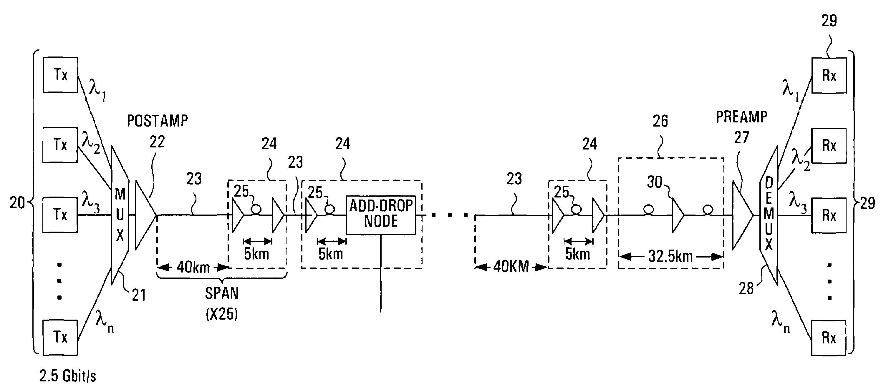
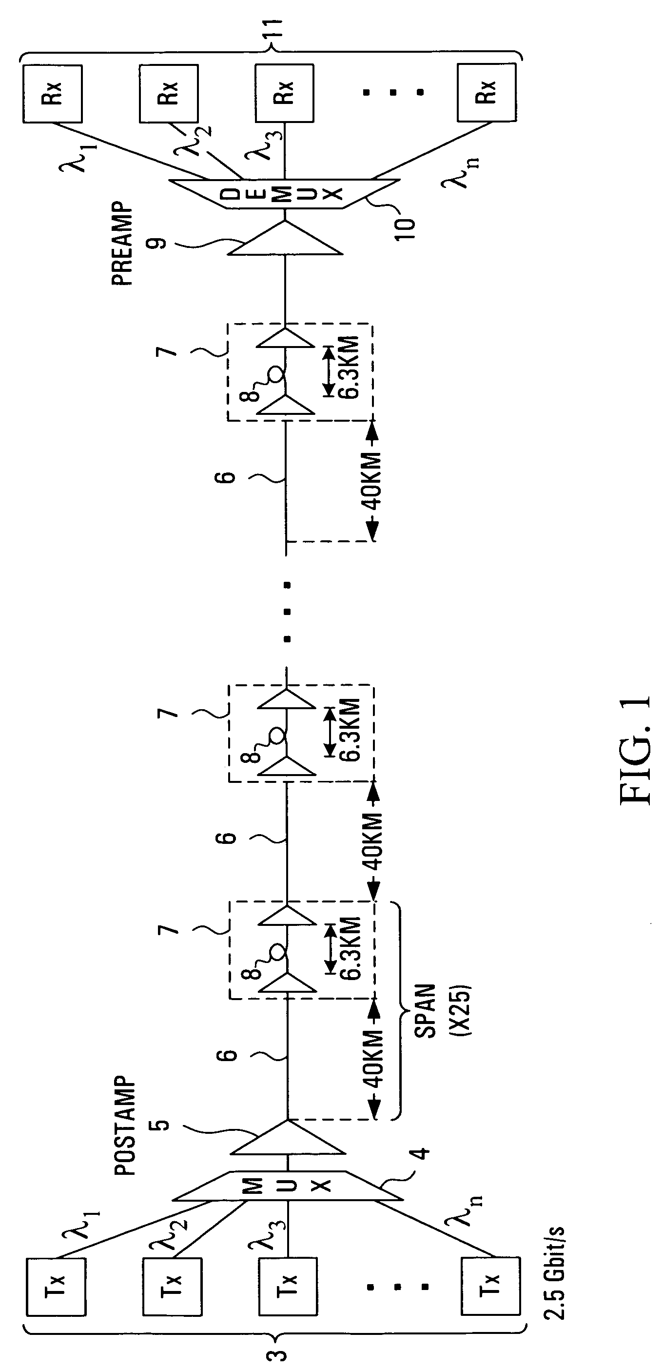
[0026]Referring to FIG. 1, the transmit path of a typical dense wavelength division multiplexed (DWDM) system spanning approximately 1000 km is shown. An array of optical transmitters 3 is connected to an optical multiplexer 4, the output of which is fed through an optical post-amplifier (POSTAMP) 5 and into an optical link comprising a plurality of serial spans extending between the post-amplifier 5 and an optical pre-amplifier (PREAMP) 9. The output of optical pre-amplifier 9 is connected to an optical demultiplexer 10 which is, in turn, connected to an array of optical receivers 11. Each serial span in the link comprises a length of optical transmission fibre 6 followed by a dispersion compensating module (DCM) 8 buried within a two-stage optical line amplifier 7.

[0027]The transmitters 3 usually consist of high resolution (or narrowband) lasers transmitting in the 1550 nm wavelength band. Narrowband transmit lasers are important for allowing close channel spacing and for minimisi...


PUM


Abstract

The invention is the novel use of dispersion compensation in a long haul wavelength division multiplexed high capacity optical transport system which has very many channels packed extremely closely together, in order to greatly reduce the deleterious effects of four-wave mixing. Four-wave mixing is an exchange of energy between nominally independent channels, arising from the fundamental fiber non-linearity, which has the effect of degrading transmission quality. Conventional systems make use of fiber dispersion compensating modules to overcome the effects of fiber dispersion. In such systems, it has been discovered that the exact distribution of fiber dispersion along the optical link (the ‘dispersion map’) strongly influences the degree of four-wave mixing, and hence the degradation in transmission quality. Furthermore, by carefully designing the dispersion map of the optical fiber link it is possible to significantly reduce the effects of four-wave mixing, allowing total system capacities and reaches to be achieved that would not otherwise be attainable. As the invention only requires the use of fiber dispersion compensating modules, the cost of implementing such a concept will not make much difference to the overall system cost.

Description

PRIORITY CLAIM[0001]This application is a continuation of U.S. application Ser. No. 09 / 469,783, filed Dec. 22, 1999 which issued as U.S. Pat. No. 6,690,886.FIELD OF THE INVENTION[0002]This invention relates to very densely packed WDM transmission systems and, more particularly, to a method and apparatus for reducing the deleterious effects of four-wave mixing.BACKGROUND OF THE INVENTION[0003]Optical fibres are increasingly being used to replace wired communications such as twisted pair and coaxial cable, as well as to enable new applications which were previously impractical such as conveying millimeter wave signals over any significant distance. Optical fibre based systems have already found widespread application in digital signal transmission. More recently, the transmission of analog signals over optical fibres has grown in importance.[0004]In the field of modern telecommunications, the emergence of fibre optics as the transmission system of choice can be attributed to two facto...

Claims


Application Information

Patent Timeline
Patent Type & Authority Patents(United States)
IPC IPC(8): H04J14/02H04B10/00H04B10/12H04B10/18H04B10/24
CPCH04B10/2503H04B10/2525H04B10/25253H04B10/2563H04J14/02H04B10/2589
Inventor GUY, MARTIN JOHN
Owner RPX CLEARINGHOUSE
Why Eureka
Try Eureka