
Apparatus and method for DC offset compensation in a direct conversion receiver

a direct conversion and receiver technology, applied in the field of telecommunications, can solve the problems of reducing the useful communication time of a battery-operated device, consuming additional electrical power, and not without potential design problems

Inactive Publication Date: 2008-01-15
QUALCOMM INC
View PDF17 Cites 15 Cited by
  • Summary
  • Abstract
  • Description
  • Claims
  • Application Information

AI Technical Summary

Benefits of technology

[0010]In one embodiment, the ADC is a serial ADC. The ADC may be a delta-sigma converter. In one embodiment, the apparatus further comprises a code converter coupled to a counter to generate an offset correction value based on the count indicative of the DC offset. In one embodiment the counter is permitted to count a pre

Problems solved by technology

However, in a mobile telecommunication environment, the additional circuitry associated with the two-stage process is costly and consumes additional electrical power, thus decreasing the useful communication time in a battery-operated device.
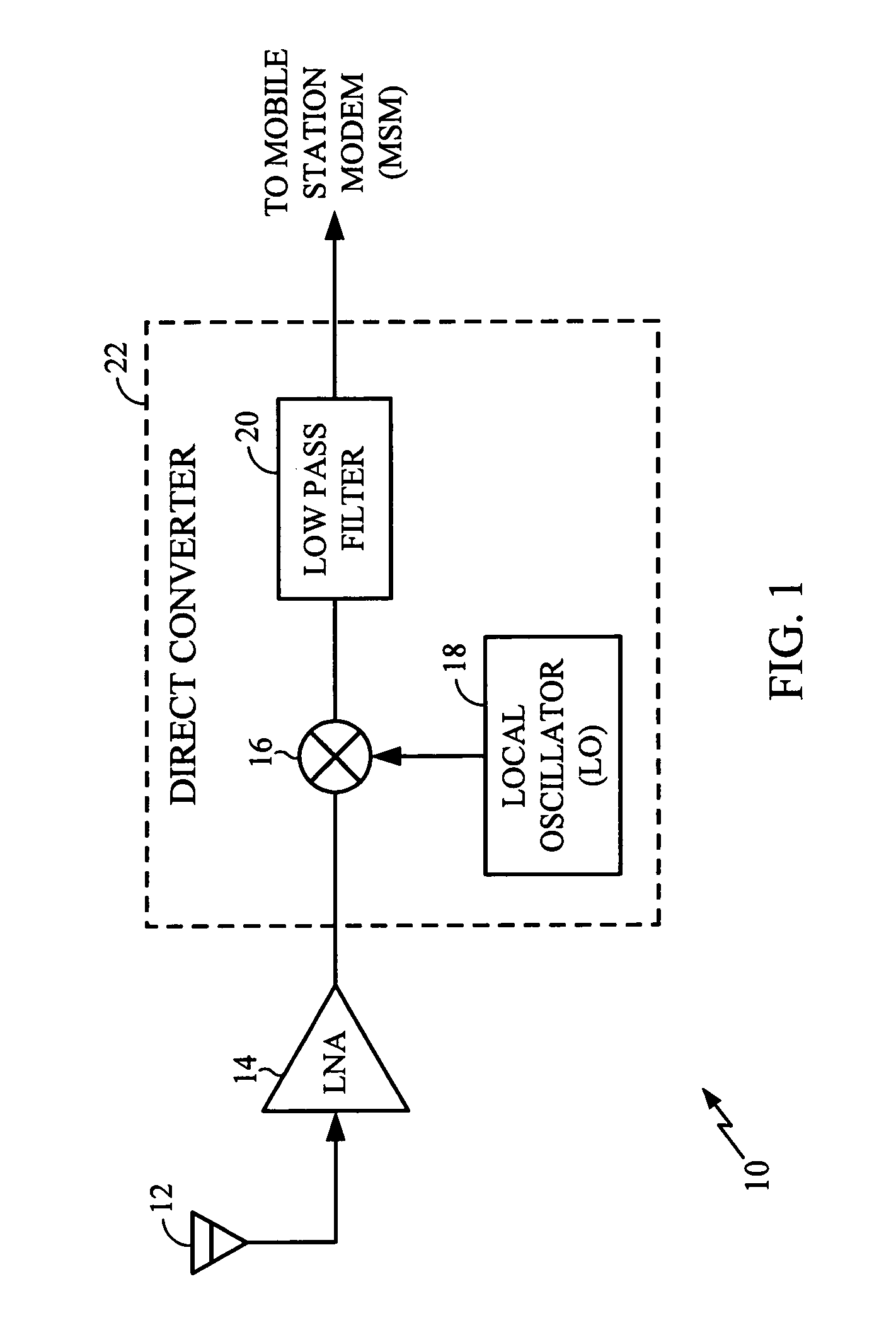
Although the direct conversion architecture simplifies circuitry, it is not without potential design problems.
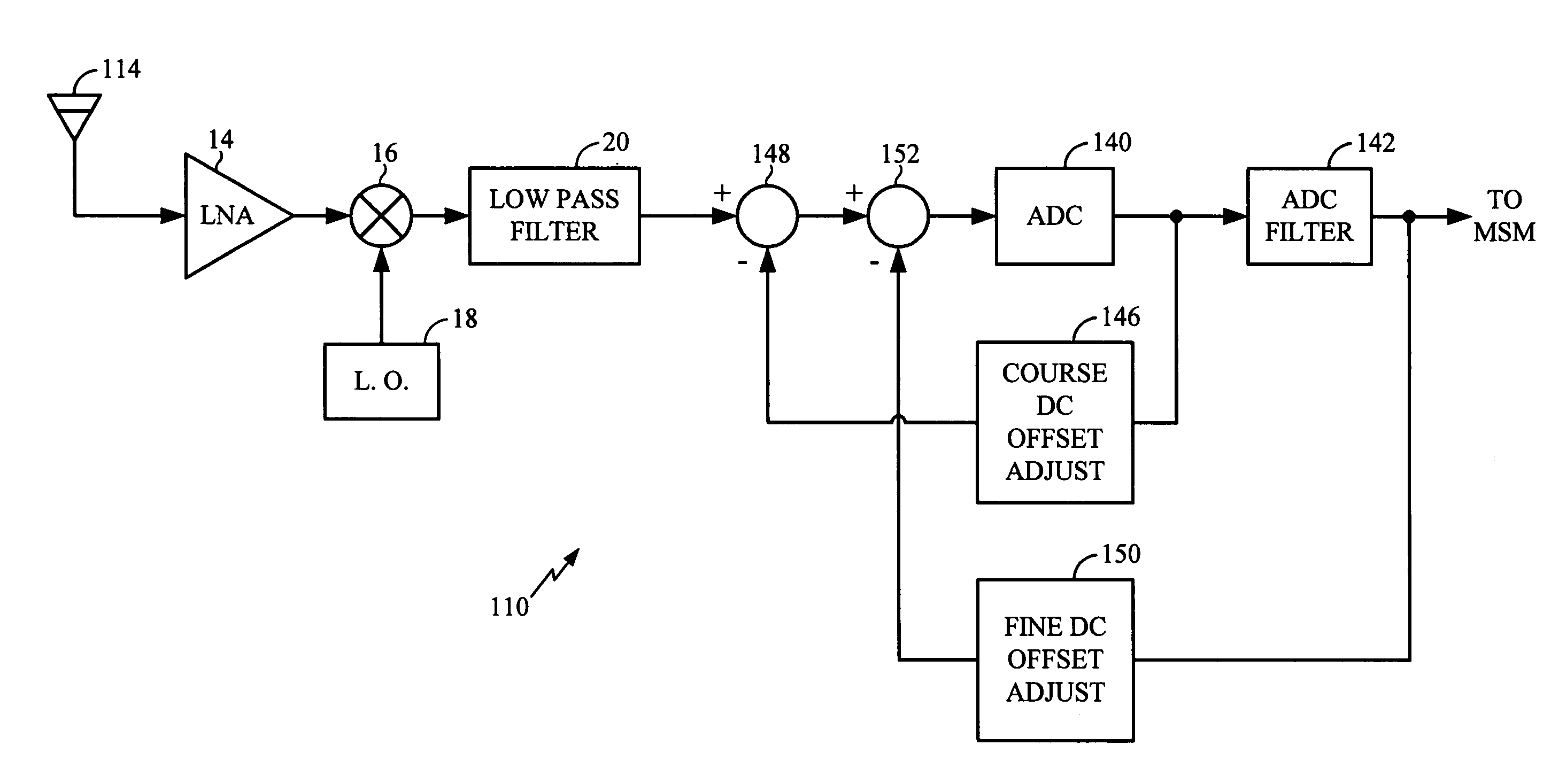
One of the problems associated with direct conversion architecture is that the output of the direct converter 22 has a high direct current (DC) offset level.
Failure to eliminate DC offsets will result in degraded signal quality, limited dynamic range due to circuit saturation and increased power consumption.

Method used


Image

  • Apparatus and method for DC offset compensation in a direct conversion receiver
  • Apparatus and method for DC offset compensation in a direct conversion receiver
  • Apparatus and method for DC offset compensation in a direct conversion receiver

Examples


Embodiment Construction

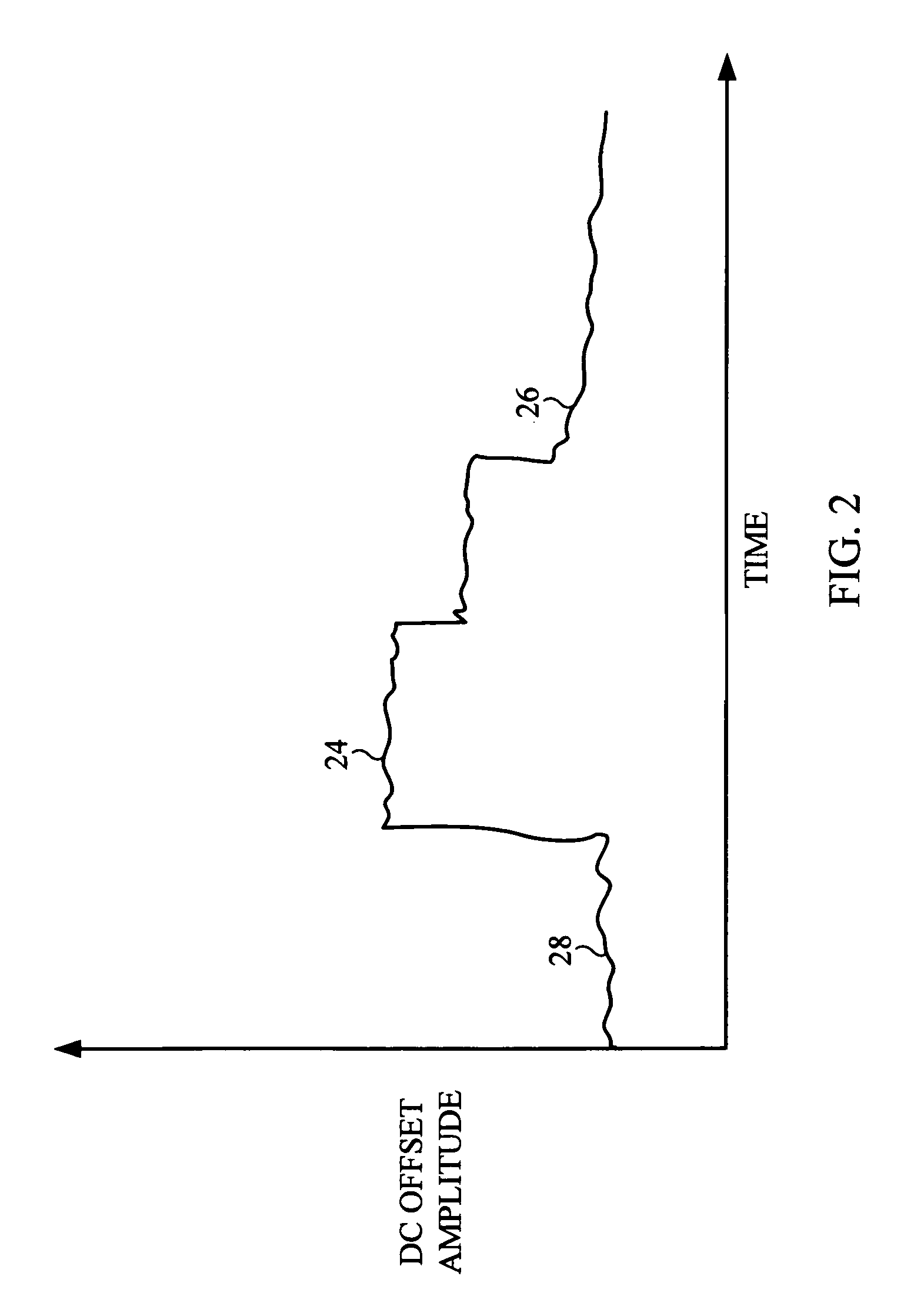
[0018]As previously discussed, direct current (DC) offsets a serious problem in a direct-to-baseband receiver architecture. The DC offset may be fixed or time-varying. The waveform of FIG. 2 illustrates the DC offset problems that may be encountered by a direct-to-baseband receiver. A portion 22 of the waveform is essentially a fixed DC offset amplitude that includes some small time-varying component. A typical receiver includes a variable gain amplifier (not shown), which has a gain control input to alter the gain in a step-wise fashion. A portion 24 of the waveform in FIG. 2 illustrates the abrupt change in DC offset amplitude that results from a sudden change in the gain setting of the variable gain amplifier. Finally, a portion 26 of the waveform in FIG. 2 illustrates a slowly changing DC offset amplitude.

[0019]The amplitude of the DC offset may be related to the gain setting within the receiver. The abrupt change in DC offset results from gain changes in the variable-gain ampli...


PUM


Abstract

An apparatus for coarse compensation of a direct current (DC) offset in a direct to baseband receiver architecture utilizes a serial analog to digital converter (ADC), such as a Delta-Sigma converter, to convert the received signal to digital form. The output of the ADC is sampled for a predetermined number of samples and a counter coupled to the ADC is incremented each time the sample generated by the ADC is a logic one. The counter is not incremented if the sample from the ADC is a logic zero. After the predetermined number of samples is obtained, the counter value is indicative of the DC offset in the received signal. The counter value may be converted by a code converter to a correction value for easy operation of a digital to analog converter (DAC). If the number of samples from the ADC is a power of two, the code converted may be readily implemented by simply inverting the most significant bit (MSB) from the counter to thereby generate a twos complement version of the counter value. The correction value is coupled to the DAC to generate a compensation signal, which is provided to the received signal path in the form of a feedback signal to compensate for the DC offset.

Description

BACKGROUND[0001]1. Technical Field[0002]The present disclosure is related generally to telecommunications and, more particularly, to a system and method for direct current (DC) offset compensation in a direct to baseband receiver.[0003]2. Description of the Related Art[0004]The conversion of a radio frequency (RF) signal to a baseband signal is part of the normal demodulation process. A conventional radio receiver converts the RF signal to baseband in two separate stages. The RF signal is first down converted to an intermediate frequency (IF) signal. The IF signal is then down converted to the baseband signal. The advantage of conversion to an IF signal is that conventional filtering may be readily employed to remove undesirable signal components. The use of a two-stage process also minimizes the direct current (DC) signal present in the baseband. However, in a mobile telecommunication environment, the additional circuitry associated with the two-stage process is costly and consumes...

Claims


Application Information

Patent Timeline
IPC IPC(8): H04B1/26H03D3/00H04B1/30H04L25/06
CPCH03D3/008H04B1/30H04L25/063H04L25/06H04B1/26
Inventor SCHLEGEL, NIKOLAIHOLENSTEIN, CHRISTIANFILIPOVIC, DANIELKASTURI, NITIN
Owner QUALCOMM INC
Learn More