
Methods for Fast and Low-Power UWB IR Baseband Receiver Synchronization

a receiver and low-power technology, applied in the direction of transmission, electrical equipment, etc., can solve the problems of low sensitivity to severe multipath fading and jamming, low probability of intercept, and difficulty in performing synchronization, etc., to achieve the effect of reducing computational complexity

Inactive Publication Date: 2011-06-23
STICHTING IMEC NEDERLAND
View PDF6 Cites 7 Cited by
  • Summary
  • Abstract
  • Description
  • Claims
  • Application Information

AI Technical Summary

Benefits of technology

[0008]It is an aim of this invention to provide a method for determining pulse position and code phase which has a lower computational complexity.
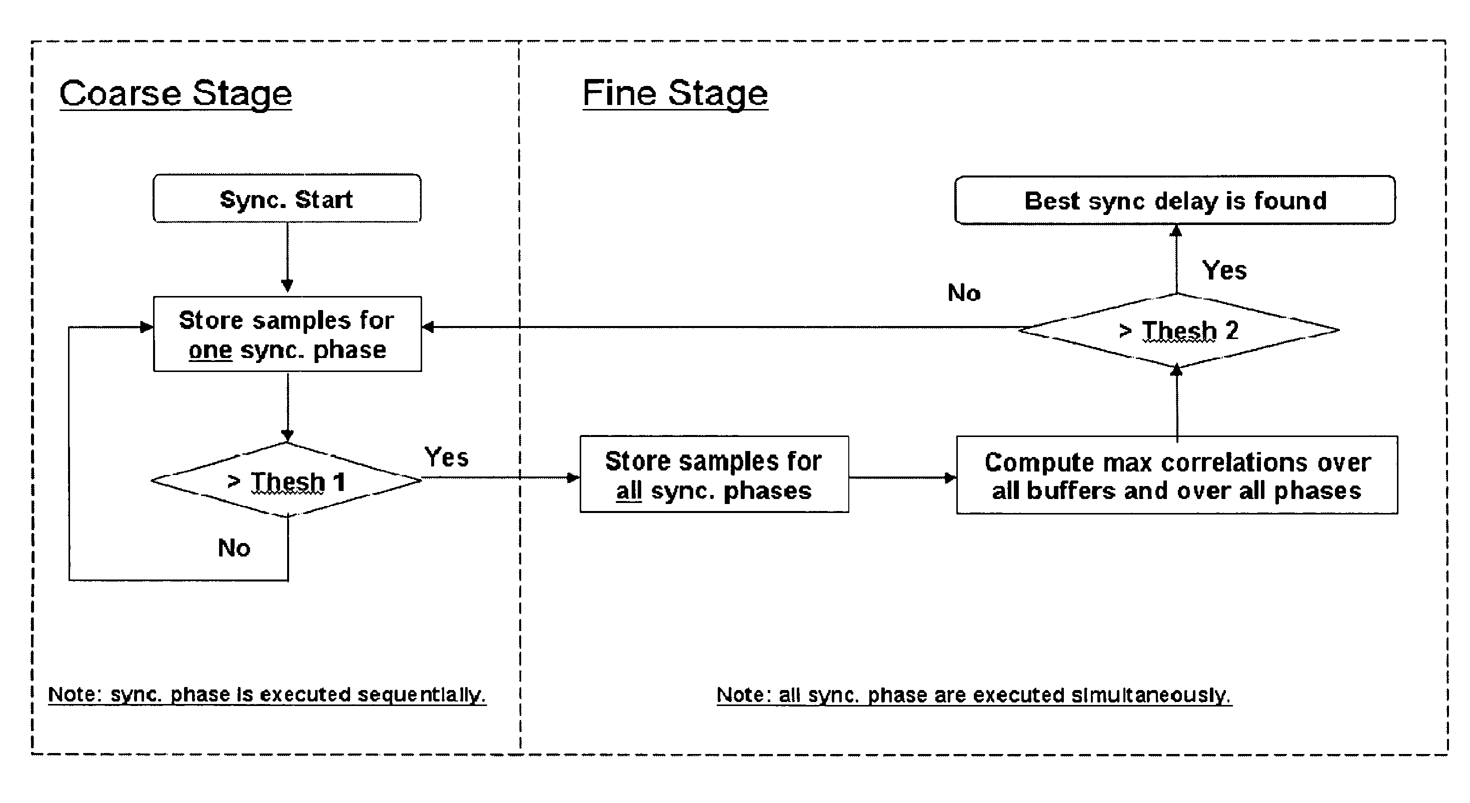
[0014]In all aspects mentioned below, the method of the invention preferably relies on the strategy to jointly search for both the pulse- and code-level positions. This minimizes the required preamble length and takes advantage of the energy accumulation resulting from coherent chip combination.
[0022]The purpose of the confirmation stage is to avoid false alarms, i.e. that presence of a signal would be detected as a result of a noise level above the noise threshold, whereas actually no signal is present. But the addition of the confirmation stage has the advantage that the pulse position and code phase which are determined in the signal detection stage anyway, are evaluated. If the confirmation stage reveals that the pulse position and code phase determined in the signal detection stage correctly indicate presence of a signal, they can be outputted towards a subsequent stage in the synchronisation process as a preliminary result, i.e. a presumed actual pulse position and presumed code phase. In this way, possibly multiple stages of the synchronization process can be skipped.

Problems solved by technology

First, they have low sensitivity to severe multipath fading and jamming.
Third, they coexist well with current wireless systems and have low probability of intercept.
Performing synchronization is especially difficult in UWB systems due to the large search space, which mainly results from the very fine resolution of the timing uncertainty region and the long spreading code.
However, this strategy suffers from a poor energy accumulation when searching for the pulse-level position.
This is undesirable for ultra-low power systems where the transmit power is very small for an isolated pulse.

Method used


Image

  • Methods for Fast and Low-Power UWB IR Baseband Receiver Synchronization
  • Methods for Fast and Low-Power UWB IR Baseband Receiver Synchronization
  • Methods for Fast and Low-Power UWB IR Baseband Receiver Synchronization

Examples


1st embodiment

1st Embodiment

No Averaging, Extensive Fine Synchronization Search

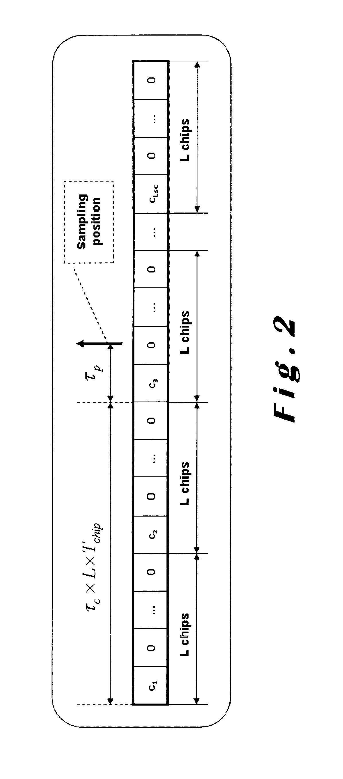
[0046]For one symbol, each symbol part is sampled N times. Note that the choice of N is a trade-off between the duty-cycling gain and the amount of symbols required for synchronization. Further, the interval between adjacent samples could be arbitrary. For example, to reduce the searching space, we could sample at every 4 possible pulse positions as shown in FIG. 3. However, to maximize the duty-cycling gain in practical implementation where the start time of the front-end is taken into account, we could consecutively sample N times instead as shown in FIG. 4.

[0047]As a result, we introduce multiple synchronization phases in order to test all possible pulse positions and cover the full length of the pulse frame. Between two consecutive phases, we shift the sampling instances by a certain amount of time to reach the next N possible pulse positions, i.e. we apply a different sampling delay. For example, as illustrated in...

2nd embodiment

2nd Embodiment

Averaging, Extensive Fine Synchronization Search

[0056]In a second embodiment of the method, we store the samples, which are averaged over M symbols, into the FIFO buffers instead of those obtained from one single symbol as introduced in the first embodiment.

[0057]The additional averaging process in this embodiment has the advantage of reducing the variance of noisy signals and thereby increases the reliability of the synchronization method in poor SNR scenarios. In fact, this averaging process is preferred to achieve reasonable synchronization errors in different channel conditions specified by the standard. Furthermore we can use this second embodiment to ease the computational burden for low speed systems. Since we average the content of the FIFOs over M symbols before performing the correlation operation, the calculation time of all correlations can be spread over M symbol periods reducing the need for high clocking frequencies.

[0058]It has to be noted though that t...

3rd embodiment

3rd Embodiment

Averaging, Short Fine Synchronization

[0059]In order to reduce the number of needed SHR symbols, we consider a third embodiment of the method where only a part of all possible synchronization phases are considered during the fine synchronization stage.

[0060]Note that in the above described embodiments of the method the fine synchronization stage doubles the number of synchronization phases compared with the coarse synchronization stage. In addition, all the synchronization phases in the coarse synchronization stage remain the same in the fine synchronization stage. Therefore, in this embodiment, we will not process all the 2L / N synchronization stages during the fine acquisition stage. Instead, we perform two steps in the fine synchronization stage. In the first step, we process L / N synchronization phases that also exist in the coarse synchronization stage. The maximum from these phases is used for roughly determining the suspected pulse positions. Then, in the second st...


PUM


Abstract

The invention relates to methods for synchronising a device to a signal containing a train of pulses representing a programmable number of repetitions of a predetermined code. Pulse position and code phase are searched for. In a first aspect, a programmable number of samples is taken per pulse frame in function of the available number of repetitions of said predetermined code. In a second aspect, the method comprises a signal detection stage from which, after performing a confirmation stage, information can be kept for a subsequent stage. In a third aspect, only a limited number of rotated versions of the predetermined code are checked, using a presumed code phase which is kept from a preceding stage.

Description

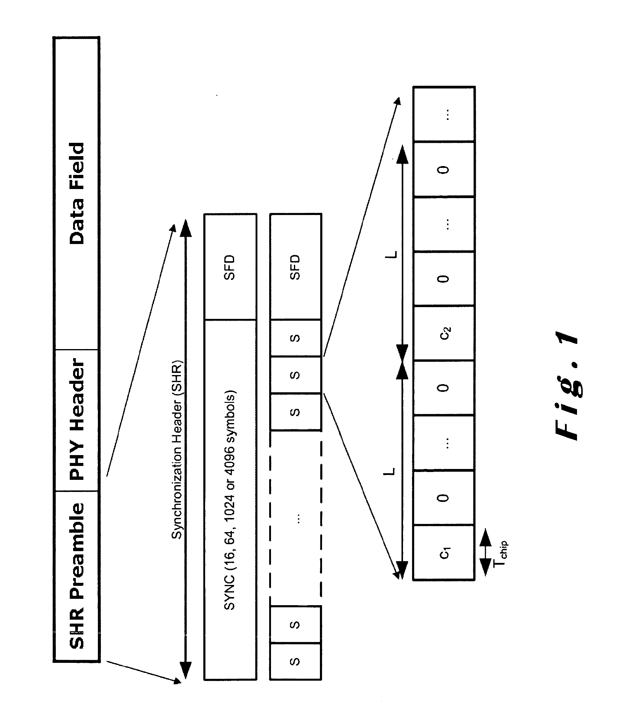
TECHNICAL FIELD[0001]The present invention relates to methods for determining pulse position and code phase in a signal, in particular for UWB IR baseband receivers.BACKGROUND ART[0002]In the IEEE 802.15.4a amendment, an ultra-wideband (UWB) physical layer (PHY) based on an impulse radio signaling scheme using band-limited pulses is specified. Furthermore, the format of an UWB frame is described, consisting of three major components: the Synchronization Header Preamble (SHR), the PHY Header (PHR) and the Physical Layer Service Data Unit (PSDU). The SHR preamble that is being added prior to the PHR could be used to aid receiver algorithms that perform packet synchronization.[0003]Ultra wideband (UWB) systems have received great attention recently due to their distinctive advantages over conventional narrowband systems. First, they have low sensitivity to severe multipath fading and jamming. Second, they enable accurate positioning and ranging. Third, they coexist well with current wi...

Claims


Application Information

Patent Timeline
IPC IPC(8): H04B1/69
CPCH04B1/7183H04B1/71637
Inventor ROUSSEAUX, OLIVIERHUANG, LIBEREKOVIC, MLADENNEIRYNCK, DRIES
Owner STICHTING IMEC NEDERLAND
Learn More