
Analog baseband filtering apparatus of multimode multiband wireless transceiver and control method thereof

a filtering apparatus and multi-mode technology, applied in the field of analog baseband filtering apparatus of multi-mode multi-band wireless transceivers, can solve the problems of affecting the operation of the filtering apparatus, and the cutoff frequency is likely to differ from the target value in the real environment, so as to improve noise cancellation, reduce the circuit area, and improve the effect of noise cancellation

Active Publication Date: 2016-06-16
SAMSUNG ELECTRONICS CO LTD
View PDF8 Cites 7 Cited by
  • Summary
  • Abstract
  • Description
  • Claims
  • Application Information

AI Technical Summary

Benefits of technology

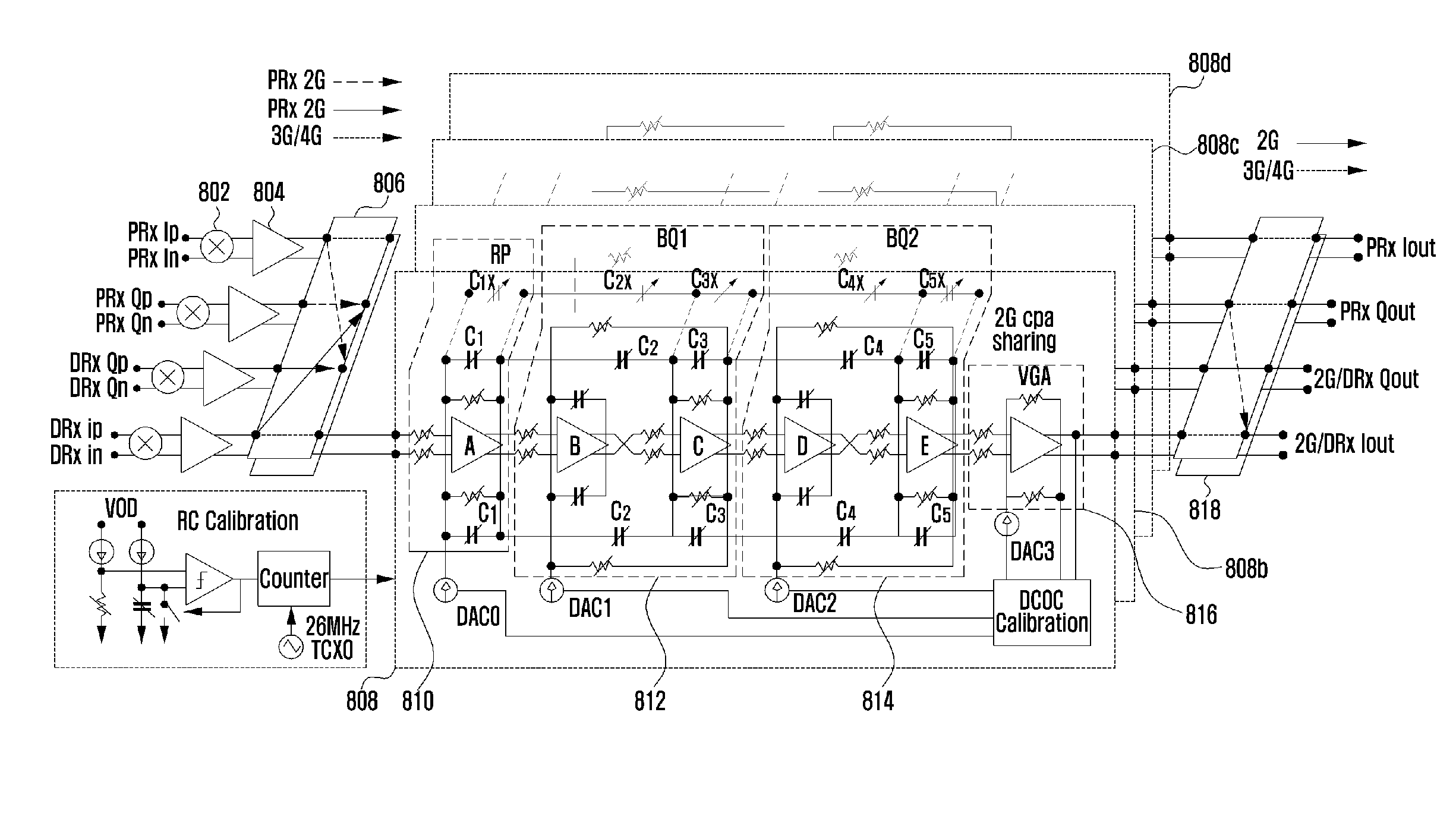
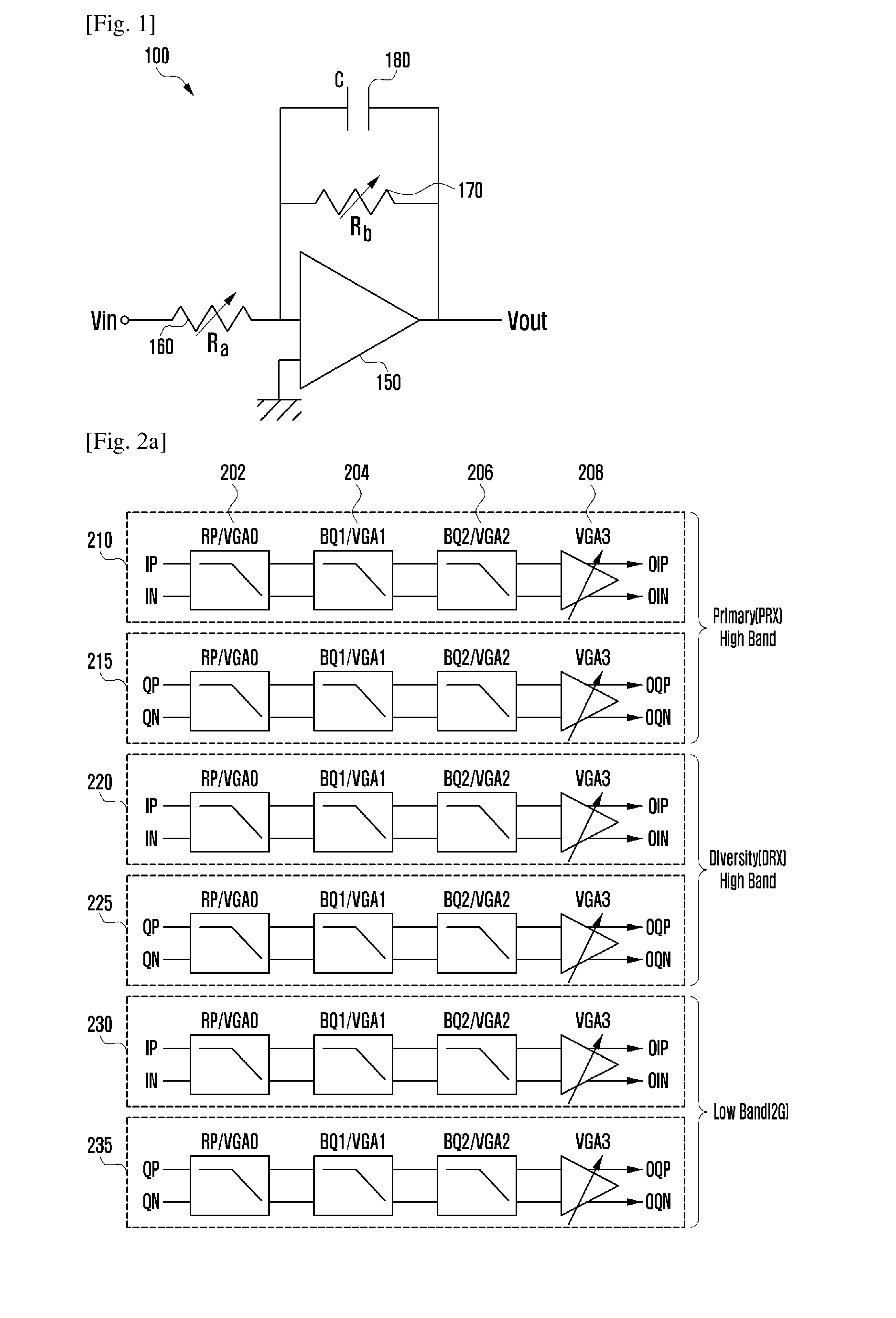
The present invention provides an analog signal filtering apparatus and method that can meet the requirements of multiple mobile communication standards for 2G, 3G, and 4G systems. It also provides a variable gain amplifier, filter circuit, and algorithm that can decrease manufacturing costs and enhance noise cancellation, making it suitable for application in multiple input multiple output (MIMO) receiver configurations. Furthermore, it provides a filter circuit for communication circuit design supporting carrier aggregation (CA) for use of carriers on multiple frequency bands.

Problems solved by technology

However, since the resistance and capacitance values determining the cutoff frequency of the analog baseband filter vary depending on the temperature and process conditions and are difficult to estimate accurately, the cutoff frequency is likely to differ from the target value in the real environment.
This means that the circuit area of the analog filter increases due to the disabled 2G mode in the state that the 3 / 4G mode is enabled, resulting in increase of manufacturing costs.
The increased circuit area also elongates the wire length so as to increase signal error and noise, resulting in degradation of signal characteristics.

Method used


Image

  • Analog baseband filtering apparatus of multimode multiband wireless transceiver and control method thereof
  • Analog baseband filtering apparatus of multimode multiband wireless transceiver and control method thereof
  • Analog baseband filtering apparatus of multimode multiband wireless transceiver and control method thereof

Examples


Embodiment Construction

[0029]Exemplary embodiments of the present invention are described with reference to the accompanying drawings in detail.

[0030]Detailed description of well-known functions and structures incorporated herein may be omitted to avoid obscuring the subject matter of the present invention. This aims to omit unnecessary description so as to make the subject matter of the present invention clear.

[0031]For the same reason, some of elements are exaggerated, omitted or simplified in the drawings and the elements may have sizes and / or shapes different from those shown in drawings, in practice. The same reference numbers are used throughout the drawings to refer to the same or like parts.

[0032]Detailed description of well-known functions and structures incorporated herein may be omitted to avoid obscuring the subject matter of the present invention. Further, the following terms are defined in consideration of the functionality in the present invention, and may vary according to the intention of...


PUM


Abstract

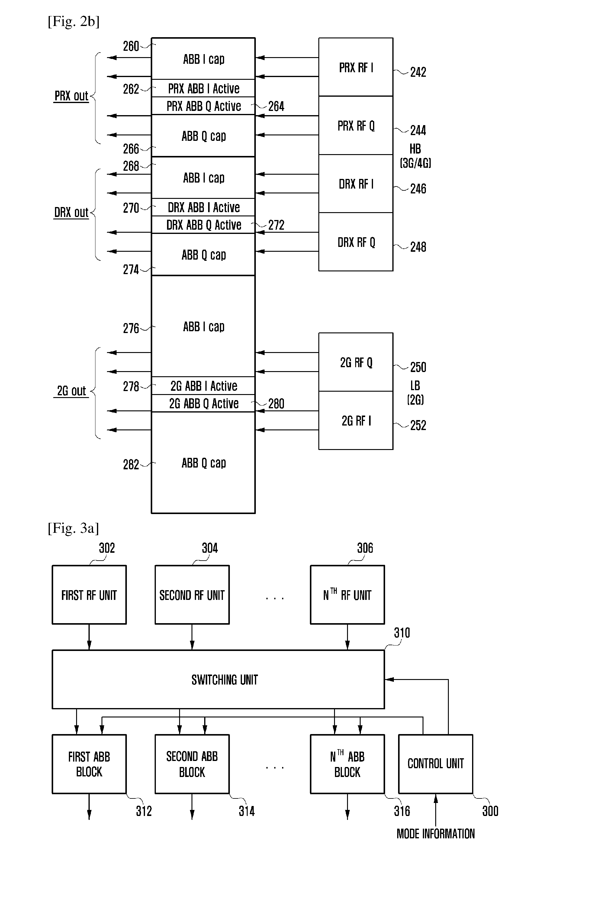
A filtering apparatus and method of a multimode multiband transceiver is provided for filtering a signal carrying an analog baseband signal. A filtering apparatus of a multimode multiband radio transceiver of the present invention includes a filtering unit which filters Radio Frequency (RF) signals on one of at least one frequency bands, a switching unit which switches the signals among at least one filter block included in the filtering unit according to a selected communication mode, and a controller which selects the communication mode and controls the switching unit. The analog signal filtering apparatus and method of the present invention is advantageous in terms of providing a variable gain amplifier, filter circuit, and algorithm capable of fulfilling the gains and bandwidths required by the baseband receiver for all mobile communication standards complied by 2G, 3G, and 4G systems.

Description

TECHNICAL FIELD[0001]The present invention relates to a wireless communication system and, in particular, to a filtering apparatus of a multimode multiband transceiver for filtering a signal carrying an analog baseband signal and a control method thereof.BACKGROUND ART[0002]A wireless communication receiver uses an analog filter to select the signal of the intended channel by removing unnecessary noise from the signal demodulated to baseband by a mixer. The accurate cutoff frequency configuration for the analog filter exerts significant influences to the system performance.[0003]Typically, a filter has an input-to-output gain varying, as the frequency increases, and is provide with a pass band and a stop band. The term ‘cutoff frequency (fc)’ denotes a boundary frequency between the pass band and the stop band. In the case of Low Pass Filter (LPF), the cutoff frequency (fc) is defined as a frequency having a gain which is 3 dB lower than then gain of the direct current or low freque...

Claims


Application Information

Patent Timeline
IPC IPC(8): H03H11/12H03H11/04
CPCH03H11/0405H03H11/12H03H7/24H03H11/1252H03H11/1291H03H2011/0494H03H2250/00H03F3/45475H03F2203/45591H03H7/12H04L25/03H03H11/0455
Inventor HAN, BYUNGKIAHN, SUSEOBLEE, JONGWOO
Owner SAMSUNG ELECTRONICS CO LTD
Learn More