
Method and apparatus for generating error correction data, and a computer-readable recording medium recording an error correction data generating program thereon

a technology of error correction data and error correction data, which is applied in the direction of channel coding adaptation, coding, instruments, etc., can solve the problems of low throughput and large delay, data cannot be replayed in high quality on the decoder apparatus, and the distribution delay and packet loss occur in rtp packet transmission, etc. problems, to achieve the effect of efficient error correction and efficient calculation of error correction data

Inactive Publication Date: 2008-01-15
FUJITSU LTD
View PDF6 Cites 72 Cited by
  • Summary
  • Abstract
  • Description
  • Claims
  • Application Information

AI Technical Summary

Benefits of technology

[0027]With the foregoing problems in view, it is an object of the present invention to make it possible to realize efficient error correction in systems in which one data sender apparatus (encoder) distributes data to two or more data receiver apparatus (decoders). The invention provides efficient calculation of error correction data for the individual decoders.
[0032]According to the present invention, exclusive-OR of transmission data is cumulatively calculated independent of error correction data insertion intervals, and exclusive-OR of a calculation of the exclusive-OR at the time of the previous error correction data insertion and a calculation of the exclusive-OR at the scheduled time of the current error correction data insertion is calculated. This provides efficient calculation of such error correction data independently of difference and changes in insertion intervals of the data, so that load of the calculation is greatly reduced, and efficient error correction is realized.
[0033]In particular, even when data is transmitted to two or more destinations (data receiver apparatus), exclusive-OR between a calculation of the exclusive-OR at the time of the previous error correction data insertion and a calculation of the exclusive-OR at the scheduled time of the current error correction data insertion is obtained for each data receiver apparatus, whereby error correction data to be inserted at the present time into data which is transmitted to each data receiver apparatus that is receiving the data is easily generated. Thus, it is not necessary to cumulatively calculate exclusive-OR depending on different insertion intervals of different data receiver apparatus, so that the present invention is greatly effective.

Problems solved by technology

However, since RTP does not guarantee real-time data communication, there is a possibility that distribution delay and packet loss occurs in RTP packet transmission.
That is, even when high-quality data distribution processing is performed, if packet loss or an error occurs, data cannot be replayed in high quality on the decoder apparatus.
However, although TCP is efficient in error correction, it has problems of low throughput and large delay.
Hence, if the requested packets are retransmitted, it is probable that the packets cannot reach the destination in time.
Accordingly, the use of TCP is not sufficient to realize a real-time communication system.
However, in network circumstances in which packet loss bursts appear, it is difficult to provide high-quality media transmission.
On the other hand, in network circumstances where the transmission rate is high and the error rate is low, FEC packet overhead is increased, thereby affecting the transmission efficiency.
On the other hand, in network circumstances where the transmission rate is low and the error rate is high, data exchange relating to packet retransmission is increased, so that the transmission efficiency is affected.
Although the previous techniques are capable of performing efficient error correction with a single encoder and a single decoder being employed, the systems do not pay consideration to systems where a single encoder distributes video data to two or more decoders.
However, provided that some or all of the decoders belong to different networks, and that the quality of one of the networks is low so that the number of retransmission requests issued by a decoder belonging to the low-quality network is particularly increased, the data transmission band for the decoder is increased, thereby affecting the band of the network.
However, since the FEC technique is forward prediction, which has a strong preventative aspect against errors, the FEC technique cannot cope with suddenly increased loss which can be caused at some timings.
Further, if the insertion interval of redundant packets for other decoders is changed so as to agree with the insertion interval of a specific decoder, not only load on the encoders is increased, but also the insertion intervals for those decoders are changed, so that desired error correction is unavailable.
In addition, the change in insertion intervals of the redundant packets will change the transmission rate, so that another communication system (TCP, etc.) in the network begins using that band, thereby reducing the usable bands for streaming.

Method used


Image

  • Method and apparatus for generating error correction data, and a computer-readable recording medium recording an error correction data generating program thereon
  • Method and apparatus for generating error correction data, and a computer-readable recording medium recording an error correction data generating program thereon
  • Method and apparatus for generating error correction data, and a computer-readable recording medium recording an error correction data generating program thereon

Examples


Embodiment Construction

)

[A] One Preferred Embodiment

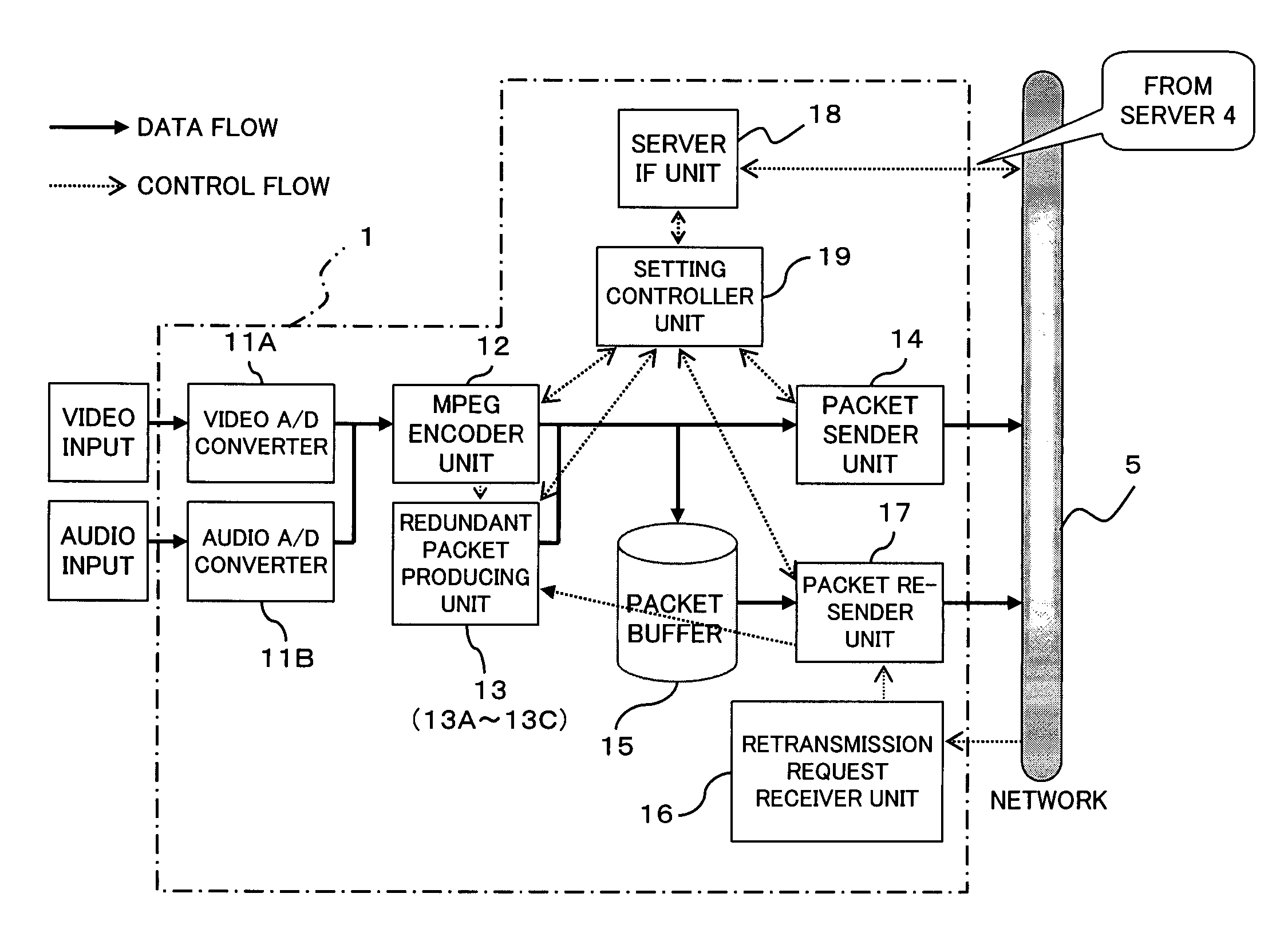
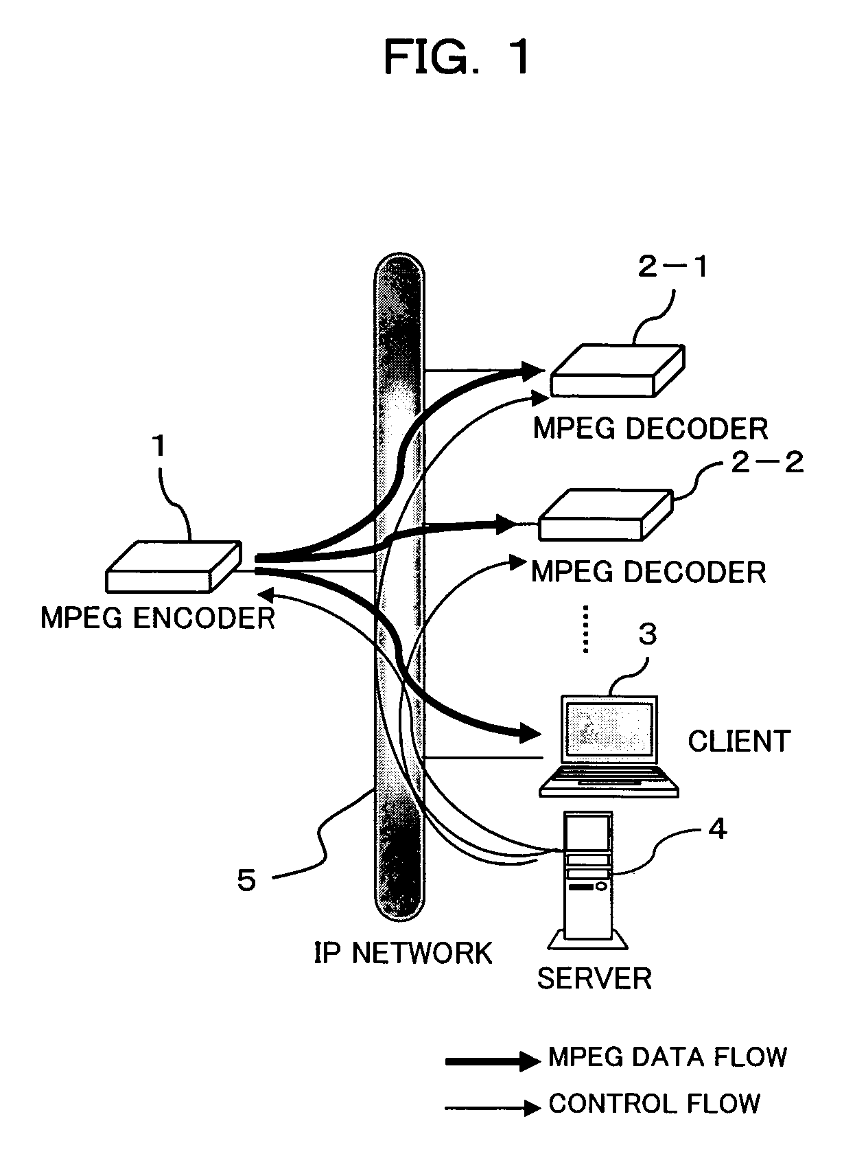
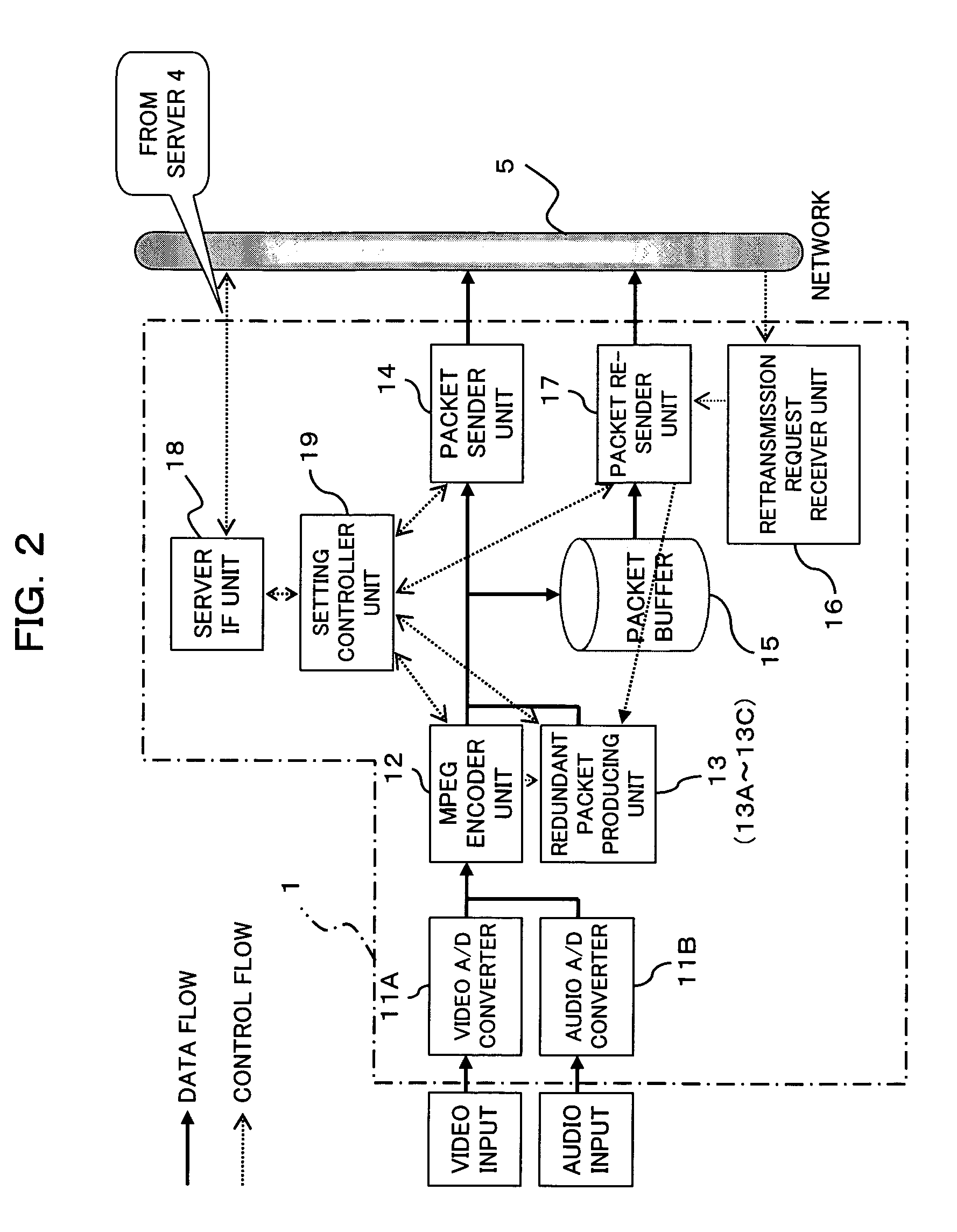
[0044]FIG. 1 is a block diagram showing a construction of an video (video) distribution system according to one preferred embodiment of the present invention. As shown in FIG. 1, the video distribution system of the present embodiment includes: MPEG encoder (data sender apparatus) 1 which makes live transmission of MPEG streaming data in packets through network 5, an IP (Internet Protocol) network with a high error rate; MPEG decoders data receiver apparatus) 2-1, 2-2, . . . and / or a client terminal (data receiver apparatus) 3 which receives, decodes, and displays the streaming data (packets) transmitted by the MPEG encoder 1; and server 4 which controls coding modes of the MPEG encoder 1 and the MPEG decoder 2 and which also controls live transmission addresses. These elements are communicably connected. Note that MPEG decoders 2-1, 2-2, . . . will be simply called “MPEG decoder 2” unless discrimination thereamong is necessary.

[0045]In the present syste...


PUM


Abstract

When error correction data, which is to be inserted into transmission data at specific intervals, is generated by calculating exclusive-OR of the transmission data, cumulative exclusive-OR of the transmission data is continuously calculated independent of the error correction data insertion intervals. Exclusive-OR between a calculation of the exclusive-OR at the time of the previous error correction data insertion and a calculation of the exclusive-OR at the time of the current error correction data insertion is calculated, thereby generating error correction data to be inserted at the present time. This provides efficient error correction data calculation.

Description

CROSS REFERENCE TO RELATED APPLICATIONS[0001]This application is based on and hereby claims priority to Japanese Patent Application No. 2004-245112 filed on Aug. 25, 2004, the contents of which are hereby incorporated by reference.BACKGROUND OF THE INVENTION[0002]1. Field of the Invention[0003]The present invention relates to a method and an apparatus for generating error correction data. The invention also relates to a computer-readable recording medium recording an error correction data generating program thereon. The invention relates particularly to a technique suitable for use in increasing resistance to errors in data transmission, such as streaming data transmission over a communication network (the Internet or the like) in which packet loss frequently occurs.[0004]2. Description of the Related Art[0005]Recently, there have been demands for data communication, such as video data communication and audio data communication, which is performed via various types of communication ...

Claims


Application Information

Patent Timeline
Patent Type & Authority Patents(United States)
IPC IPC(8): G08C25/02G08C25/04
CPCH03M13/03H03M13/095H04L1/0009H04L1/0041H04L1/0059H04L1/08H04L1/0042H04L1/1809H04L2001/0093H04L1/18
Inventor MIURA, TSUYOSHIIHARA, NORIYUKIFUJITA, SHINNAKAGAWA, AKIRAICHIKI, ATSUSHI
Owner FUJITSU LTD
Learn More