
Method and system for verification of soft error handling with application to CMT processors

a technology of soft error handling and cmt processor, applied in error detection/correction, program control, instruments, etc., can solve the problems of insufficient approach for chip multi-threading (cmt) processor, inability to easily model soft error events, and inability to properly handle errors encountered by error encountering threads

Active Publication Date: 2008-01-15
ORACLE INT CORP
View PDF4 Cites 48 Cited by
  • Summary
  • Abstract
  • Description
  • Claims
  • Application Information

AI Technical Summary

Benefits of technology

[0010]Yet another embodiment provides a diagnostic program generator comprising computer code. The diagnostic program generator generates a diagnostic program. The diagnostic program comprises a plurality of randomly generated instructions interspersed with error directives. Each error directive comprises an instruction causi

Problems solved by technology

Various subcircuits in microprocessors such as register files and memory buffers store data subject to corruption by soft errors.
Soft errors occur when ionizing radiation causes a node in a memory array to invert is logical value.
However, an ISS or reference architecture cannot easily model soft error events because they are not always coupled with a specific instruction and because of their inherently random nature.
This presents a challenge in verifying hardware functionality pertaining to detection, correction, and logging of such errors, referred to collectively herein as soft error handling.
This approach is not adequate for chip multi-threading (CMT) processors because of the presence of multiple concurrent threads, which could be executing completely independent programs.
Here, the proper error handling by the error encountering thread could be hampered by events on other threads.
Furthermore, an error on one thread could “leak” to another thread causing spurious logging or functional incorrectness.
For example, if a thread sees an error which is then improperly reported to a different thread, the second thread will behave as if the error occurred during the execution of its own program, potentially resulting in data corruption.

Method used


Image

  • Method and system for verification of soft error handling with application to CMT processors
  • Method and system for verification of soft error handling with application to CMT processors
  • Method and system for verification of soft error handling with application to CMT processors

Examples


Embodiment Construction

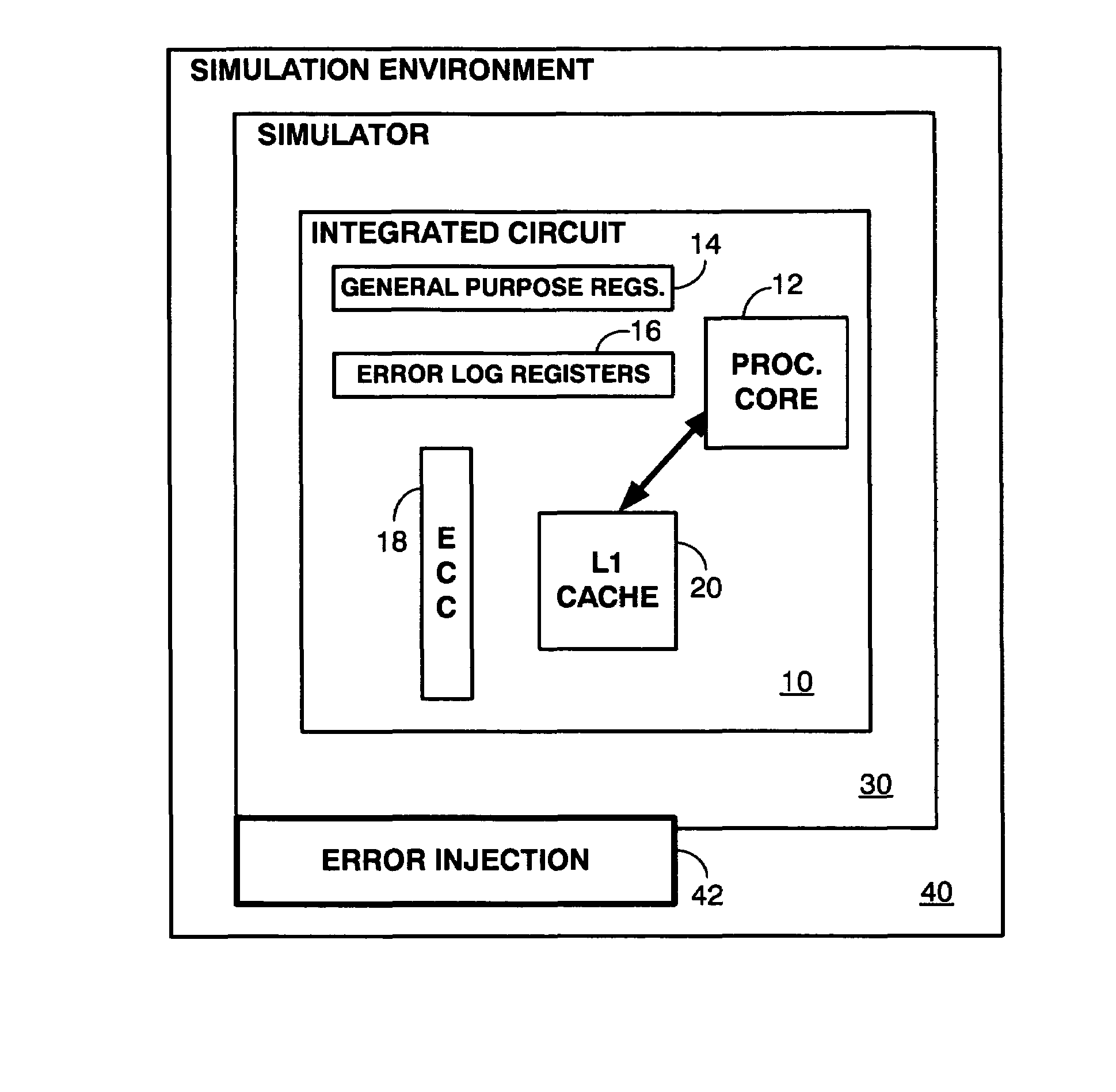
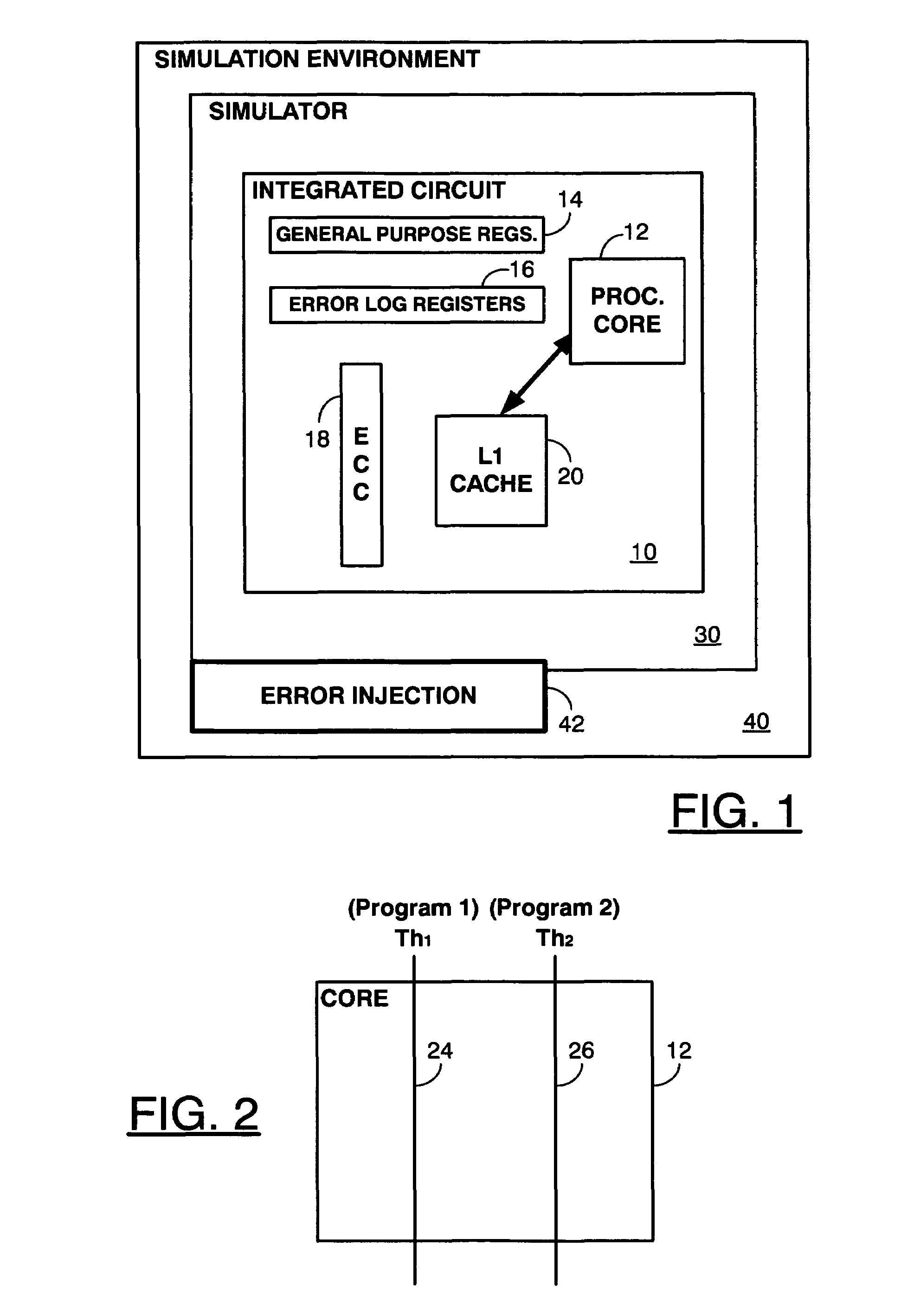
[0021]FIG. 1 is a schematic of an exemplary system and microprocessor design to illustrate a system and environment for an exemplary soft error handling verification method and system. Simulation environment 40 is a software and hardware platform executing a software simulator 30 that simulates the operation of an integrated circuit (IC) design 10. Simulation environment 40 may also include other tools and environmental variables that control or modify the operation of simulator 30. Specifically, error injection module 42 provides a mechanism by which soft errors can be injected in IC design 10 during simulation.

[0022]Simulator 30 receives an IC design 10 and mimics the behavior of an actual integrated circuit based on the design. Thus, a software model of the integrated circuit design 10 is received and is maintained by simulator 30. In other words, simulator 30 operates a virtual IC based on IC design 10.

[0023]An exemplary IC design 10 shows a processor core 12, a plurality of gen...


PUM


Abstract

A method provides for verifying soft error handling in an integrated circuit (IC) design. A diagnostic program is executed on a virtual IC based on the IC design using a simulator. A soft error is injected into the virtual IC to trigger hardware error correction in the virtual IC and a software exception. A record of a type and a location of the soft error at the time of the injecting is created. The error log generated by hardware error correction is then compared with the record of injected error, the hardware error correction being part of the virtual IC. An IC design flaw is indicated when a discrepancy exists between the error log and the record of the injected error.

Description

BACKGROUND OF THE INVENTION[0001]1. Field of the Invention[0002]The present invention relates generally to verifying soft error handling in integrated circuit designs. Specifically, the present invention provides a system and method for verification of soft error handling using a diagnostic program run in an integrated circuit simulator.[0003]2. Description of the Related Art[0004]Various subcircuits in microprocessors such as register files and memory buffers store data subject to corruption by soft errors. Soft errors occur when ionizing radiation causes a node in a memory array to invert is logical value. Most hardware has embedded logic to detect, correct and log such errors and notify the software of such an event through exceptions. Instruction set simulators (ISS) are often used to verify the proper functioning of the chip in conjunction with the virtual IC described below which models the physical implementations of the chip. However, an ISS or reference architecture cannot ...

Claims


Application Information

Patent Timeline
IPC IPC(8): G06F17/50G01R31/28G06F11/00
CPCG06F11/261G06F11/263
Inventor JAIN, PRASHANTCHAN, KENNETH K.PALANISAMY, KUMARASAMYJU, CHISHEIN
Owner ORACLE INT CORP
Learn More