
Cargo unloading apparatus and method

Inactive Publication Date: 2008-01-22
SMITH FRED P
View PDF18 Cites 7 Cited by
  • Summary
  • Abstract
  • Description
  • Claims
  • Application Information

AI Technical Summary

Benefits of technology

[0014]The extra length of the flexible member at the rear of the cargo area may be unrolled back toward the front of the cargo area to cover the load. If desired, the flexible member may be secured (e.g. by bungee cords, rope, and the like) to keep the load from blowing out of the cargo area during transport.
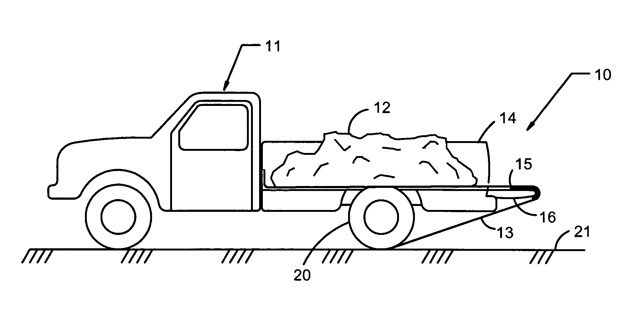
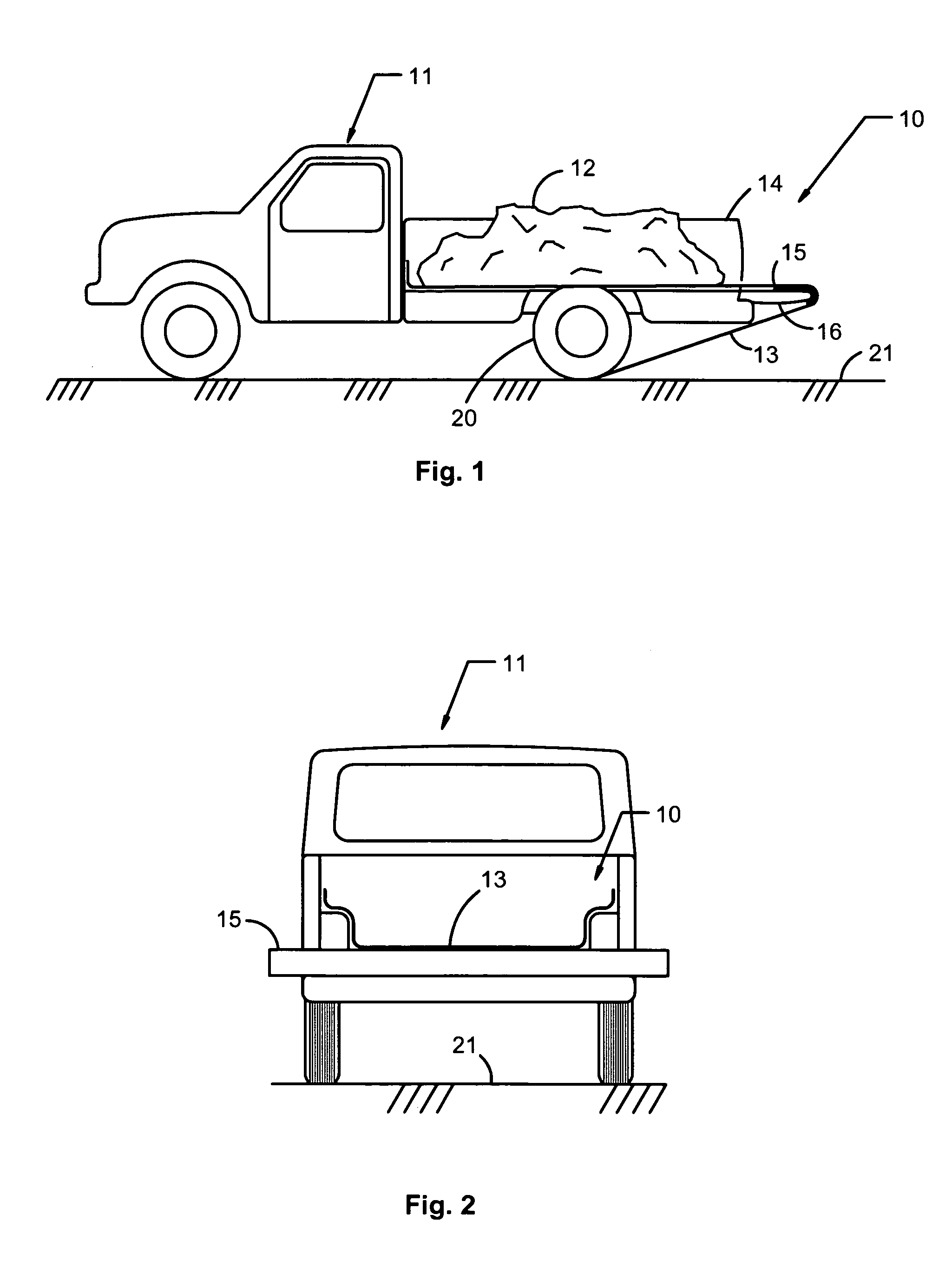
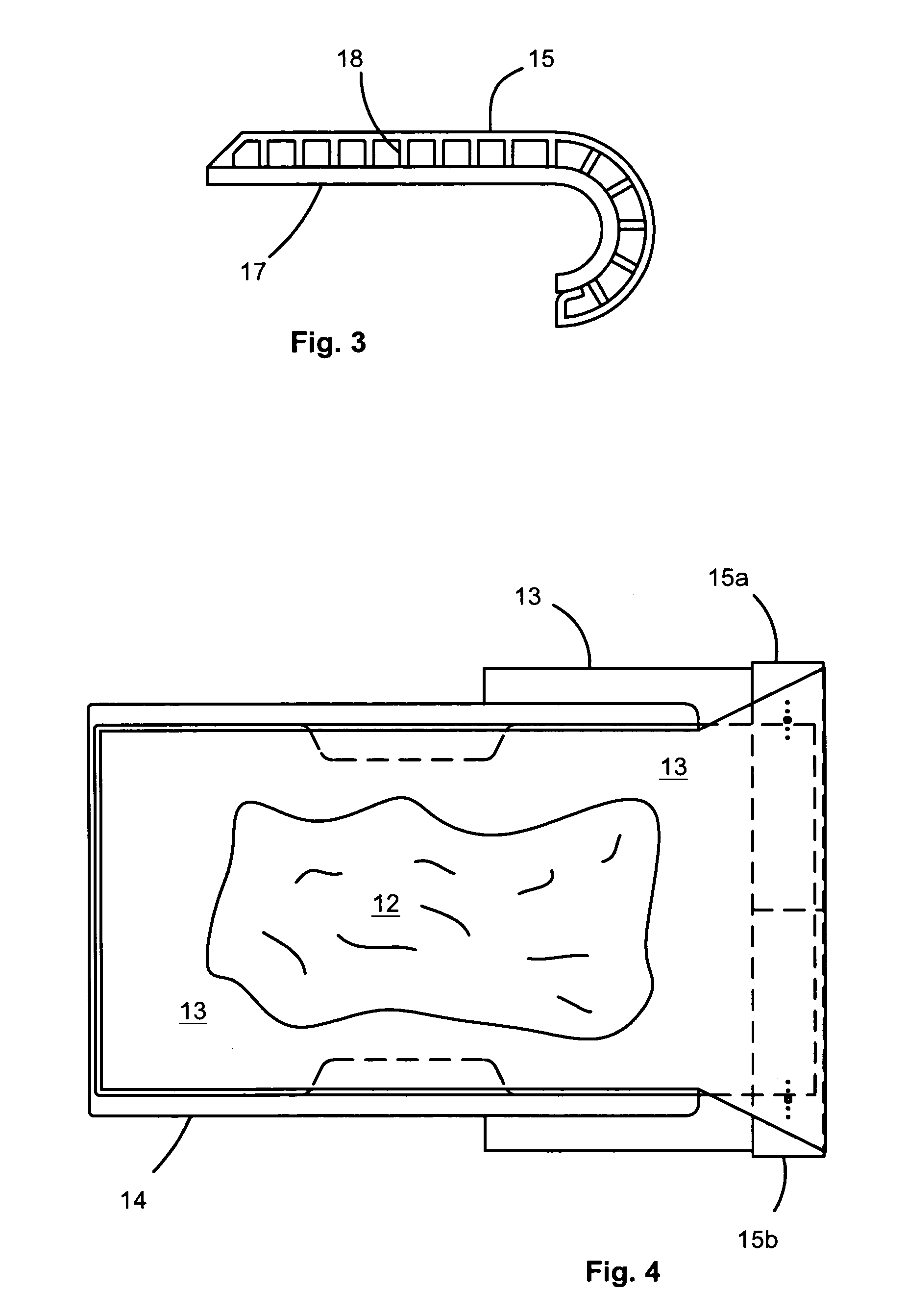
[0017]The friction-reducing member in accordance with the present invention may accomplish several purposes. A friction-reducing member may reduce frictional forces and associated wear by facilitating movement of the flexible member around the tailgate. A friction-reducing member may protect the finish of the tailgate. A friction-reducing member may also extend side to side in a lateral direction a distance greater than the width of the tailgate. In certain embodiments, a friction-reducing member having a width greater than the tailgate may reduce stress concentrations at the corners of the tailgate that may otherwise rip flexible members made of selected materials.
[0020]Accordingly, the present invention is a new and improved unloading device to unload a cargo area with minimal manual effort. The instant invention requires no modifications to the vehicle. Certain embodiments may be installed for use in less than one minute and may be taken off and stored out of sight in less than one minute. The present invention may be readily adaptable to all pickup trucks, trailers, cars, as well as many other types of vehicles. It may be noted that certain embodiments of the present invention automatically hold the tailgate down when in use. Thus, eliminating the need for other hold down straps required by manual crank unloaders. Furthermore, the present invention is inexpensive to manufacture. The present invention also provides for covering of the load during transit. Moreover, the present invention provides powered unloading with minimal manual labor.

Problems solved by technology

The same does not hold true, however, for unloading the materials from vehicles.
Unloading in this manner is labor intensive, time consuming, and dangerous due to the manual labor involved and the requirement that the unloader climb on top of the load.
Those that use a hydraulic cylinder to do the dumping have required the bed to be raised destroying the cab to body lines and the looks of the truck.
Even the hinge system in the inventor's U.S. Pat. No. 6,059,371 may be expensive and require modifications to the vehicle to hinge the cargo area or truck bed to allow the load to be dumped.
Each of the foregoing devices is either costly to manufacture, manually powered, limited in maximum capacity, dependent on extensive modifications to the vehicle, or the like.

Method used


Image

  • Cargo unloading apparatus and method
  • Cargo unloading apparatus and method
  • Cargo unloading apparatus and method

Examples


Embodiment Construction

[0032]It will be readily understood that the components of the present invention, as generally described and illustrated in the Figures herein, could be arranged and designed in a wide variety of different configurations. Thus, the following more detailed description of the embodiments of the system and method of the present invention, as represented in FIGS. 1 through 10, is not intended to limit the scope of the invention, as claimed, but is merely representative of selected embodiments of the invention.

[0033]Referring to FIG. 1, a cargo unloader 10 in accordance with the present invention may be applied to a vehicle 11. For illustrative purposes, a pickup truck 11 will be the vehicle 11 illustrated in the Figures. However, it is understood that the present invention maybe applied to any vehicle such as a flatbed truck, trailer, car, or any other type of load carrier.

[0034]A flexible member 13 may be placed in the cargo area 14 of a vehicle 11. In certain embodiments, the flexible...


PUM


Abstract

An apparatus and method to facilitate unloading material from the cargo area (e.g. bed) of a vehicle. The apparatus may include a flexible member placed to line the bottom of the cargo area before a load is placed therein. After moving the vehicle to a desired location, a friction-reducing member may be placed to extend across the rear edge of the cargo area (e.g. the rear edge of an open tailgate). One end of the flexible member may be wrapped around the friction-reducing member and placed just behind the rear wheels of the vehicle. The vehicle may then be moved in reverse. The wheels of the vehicle roll over the flexible material, fixing one end thereof to the ground. The friction reducing member acts like a pulley (whether rolling with, or simply sliding with respect to, the flexible member) at the edge of the moving tailgate, drawing the flexible member and associated load out of the cargo area of the vehicle.

Description

RELATED APPLICATIONS[0001]This application claims the benefit of U.S. Provisional Patent Application Ser. No. 60 / 441,490 filed on Jan. 21, 2003 and entitle CARGO UNLOADER.BACKGROUND[0002]1. The Field of the Invention[0003]This invention relates to cargo transporting and, more particularly, to novel systems and methods for unloading material from a cargo area.[0004]2. The Background Art[0005]Many materials such as sand, gravel, dirt, and grain are commonly transported in pickup trucks, trailers, and the like. Other bulk materials commonly transported include trash, yard waste, manure, mulch, bark, building materials, hay, feed, firewood, equipment, tools, palletized materials, and the like. These materials are generally loaded in bulk at a distribution point by a front-end loader, overhead bin, forklift, or the like. Thus, loading of the material into the cargo area of a vehicle is generally accomplished without much effort.[0006]The same does not hold true, however, for unloading th...

Claims


Application Information

Patent Timeline
IPC IPC(8): B60P1/00B60P1/38
CPCB60P1/38
Inventor SMITH, FRED P.
Owner SMITH FRED P
Learn More