Electrical connector having a fastening assembly and a metal housing that pertain to different parts

a technology of electrical connectors and metal housings, applied in the direction of electrical apparatus, connection, coupling device connections, etc., can solve the problems of insufficient intensity and elasticity, material waste, and inability to achieve the effect of saving materials, so as to reduce manufacturing costs

Inactive Publication Date: 2008-01-22
TSAI CHOU HSUAN
View PDF11 Cites 18 Cited by
  • Summary
  • Abstract
  • Description
  • Claims
  • Application Information

AI Technical Summary

Benefits of technology

[0011]It is therefore an object of the invention to provide an electrical connector having a fastening assembly and a metal housing that pertain to different parts such that the manufacturing cost is reduced.
[0013]Still another object of the invention is to provide an electrical connector having an engaging element and a metal housing that pertain to different parts such that the manufacturing cost is reduced.
[0014]Yet still another object of the invention is to provide an electrical connector having an engaging element and a metal housing that pertain to different parts, wherein the engaging element is assembled and positioned from a backside of the plastic base such that the engaging element has a good positioning effect.
[0015]Yet still another object of the invention is to provide an electrical connector having an engaging element, which has an elastic engaging piece, wherein the elastic engaging piece is elastically moved to press the plastic base such that the force of fastening the transmission cable plug may be maximized
[0017]According to the above-mentioned structure, because the engaging element and the fastening assembly pertain are members different from the metal housing, a large-area metal housing may be made of an ultra-thin metal plate, and the manufacturing cost is reduced greatly. The engaging element and the grounding element may be made of a thicker metal plate or other suitable materials such that the sufficient elasticity and rigidity can be obtained. Furthermore, the material can be reduced and the plating cost may be reduced because the fastening assembly and the metal housing pertain to different parts.

Problems solved by technology

1. Each of the top and bottom surfaces of the metal housing 20 is pressed to form two elastic engaging pieces 21 for engaging with the engagement holes 36 of the USB plug 35, and the lower edges of the metal housing 20 are integrally extended to form the fastening hooks 24. So, the plastic engaging pieces 21 and the fastening hooks 24 must have the proper intensity in order to achieve the stable engaging and hooking effects. In this way, the metal housing 20 cannot be formed by a thinner plate, or the elastic engaging piece 21 and the fastening hook 24 may have insufficient intensity and elasticity, and the effect of saving the material cannot be achieved.
2. Because the fastening hooks 24 are integrally formed at the lower edges at two sides of the metal housing 20 by way of pressing, the two side plates have to be long enough such that the fastening hooks 24 can be formed, and the material is thus wasted.
3. Because the fastening hooks 24 are integrally formed at the lower edges at two sides of the metal housing 20, tin has to be plated on the fastening hooks 24 such that the fastening hooks 24 may be electrically connected to the circuit board. Thus, the plating cost has to be added.
4. As shown in FIG. 3, when the USB plug 35 is pulled out and thus pushes the elastic engaging pieces 21 and 31, the elastic engaging pieces 21 and 31 elastically move according to the elasticity thereof, and the baffle 11 is not pressed. The engaging intensity completely comes from the intensity thereof, so each of the elastic engaging pieces 21 and 31 must have the sufficient thickness to provide the sufficient engaging force.

Method used


Image

  • Electrical connector having a fastening assembly and a metal housing that pertain to different parts
  • Electrical connector having a fastening assembly and a metal housing that pertain to different parts
  • Electrical connector having a fastening assembly and a metal housing that pertain to different parts

Examples


first embodiment

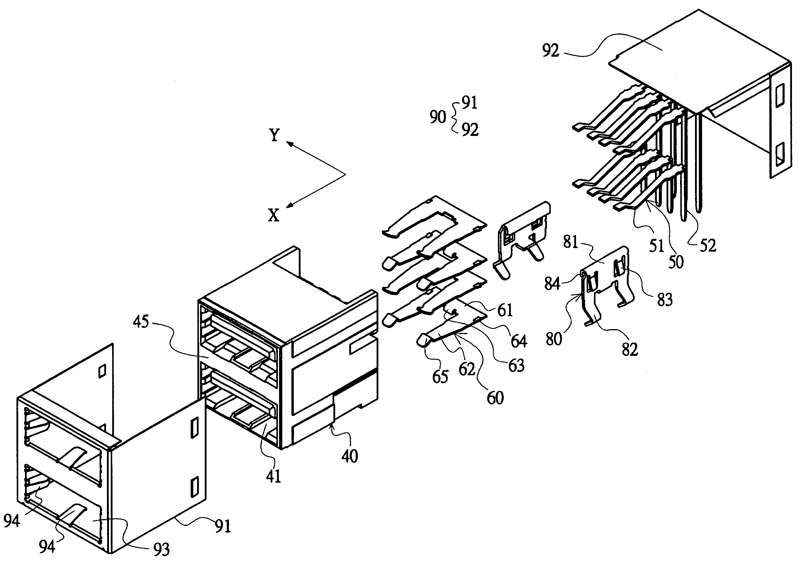
[0052]Referring to FIGS. 4 to 6, a dual-layer USB electrical connector according to the invention is to be electrically connected to a USB plug 35 having at least one engagement hole 36. The dual-layer USB electrical connector includes a plastic base 40, four engaging elements 60, two fastening assemblies 80 and one metal housing 90.

[0053]At least two connection slots 41 and a plurality of terminals 50 are disposed within the plastic base 40. The front end of the connection slot 41 is an inserting port into which the USB plug 35 may be inserted. As shown in FIGS. 7 and 8, the rear end of each connection slot 41 is formed with two positioning slots 42 and one stopping surface 43. A baffle 45 is disposed or formed between the two connection slots 41. In addition, each of the two sides of the rear end of the plastic base 40 is formed with an inverse-L-shaped engaging slot 46 extending from back to front. Each terminal 50 has a contact 51 located at the connection slot 41 and a pin port...

eleventh embodiment

[0079]Referring to FIGS. 27 and 28, an audio / video transmission cable socket (e.g., a high definition multimedia interface (HDMI)) according to the invention includes a plastic base 40, a metal housing 90 and two fastening assemblies 80. The plastic base 40 is formed with a connection slot 41. The metal housing 90 is composed of a front housing 91 and a rear housing 92 that are assembled together. The front housing 91 is formed with an opening 93 through which the connection slot 41 is exposed to the outside. The fastening assemblies 80 are separated from the metal housing before the connector is assembled, positioned at two sides of the plastic base 40 and in contact with the metal housing. The fastening assemblies 80 may be bonded to a circuit board using the surface mount technology (SMT).

[0080]As shown in FIG. 29, the twelfth embodiment of the invention is an electrical connector to be connected to a transmission cable plug of an earphone, a speaker or a microphone. The connecto...


PUM


Abstract

An electrical connector to be electrically connected to a transmission cable plug. The connector includes a plastic base, a metal housing and at least one fastening assembly. At least one connection slot and a plurality of terminals are formed on the plastic base. Each of the terminals has a pin portion extending out of the plastic base. The metal housing covers the plastic base while exposing the at least one connection slot of the plastic base and the pin portions of the terminals to the outside. The at least one fastening assembly contacts the metal housing and thus is electrically connected to a circuit board. The at least one fastening assembly and the metal housing pertain to different parts.

Description

BACKGROUND OF THE INVENTION[0001]1. Field of the Invention[0002]The invention relates to an electrical connector, and more particularly to an electrical connector having a metal housing.[0003]2. Description of the Related Art[0004]Referring to FIGS. 1 and 2, a dual-layer USB (Universal Serial Bus) electrical connector into which a convention USB plug is inserted includes a plastic base 10, a metal housing 20 and a front fitting part 30. The plastic base 10 has a baffle 11 and two connection slots 12 at a front end thereof. A plurality of terminals 13 is disposed in the plastic base 10. The metal housing 20 covers the plastic base 10 and enables the connection slots 12 of the plastic base and a pin portion of each terminal 13 to be exposed to the outside. The metal housing 20 has top and bottom surfaces each formed with two elastic engaging pieces 21 by way of pressing. The elastic engaging piece 21 is formed with a projecting engaging portion 22 at a portion near a distal end thereo...

Claims


Application Information

Patent Timeline
Patent Type & Authority Patents(United States)
IPC IPC(8): H01R13/60
CPCH01R12/716H01R12/7029H01R25/006
Inventor TSAI, CHOU HSUAN
Owner TSAI CHOU HSUAN
Why Eureka
Try Eureka