LED dimming control technique for increasing the maximum PWM dimming ratio and avoiding LED flicker

a technology of led dimming control and maximum pwm, which is applied in the direction of electric variable regulation, process and machine control, instruments, etc., can solve the problem of delay td and reduce the time available for the led driver

Active Publication Date: 2008-01-22
ANALOG DEVICES INT UNLTD
View PDF7 Cites 82 Cited by
  • Summary
  • Abstract
  • Description
  • Claims
  • Application Information

AI Technical Summary

Benefits of technology

[0016]In accordance with another embodiment of the disclosure, the synchronizing circuit may hold the control input of the latch at a first level during an inactive portion of the PWM dimming control signal, and may allow the control input to go to a second level causing the switching circuit to quickly turn on in response to an active edge of the PWM dimming control signal.

Problems solved by technology

However, the delay Td reduces time available for the LED driver to reach the maximum inductor current.

Method used


Image

  • LED dimming control technique for increasing the maximum PWM dimming ratio and avoiding LED flicker
  • LED dimming control technique for increasing the maximum PWM dimming ratio and avoiding LED flicker
  • LED dimming control technique for increasing the maximum PWM dimming ratio and avoiding LED flicker

Examples


Embodiment Construction

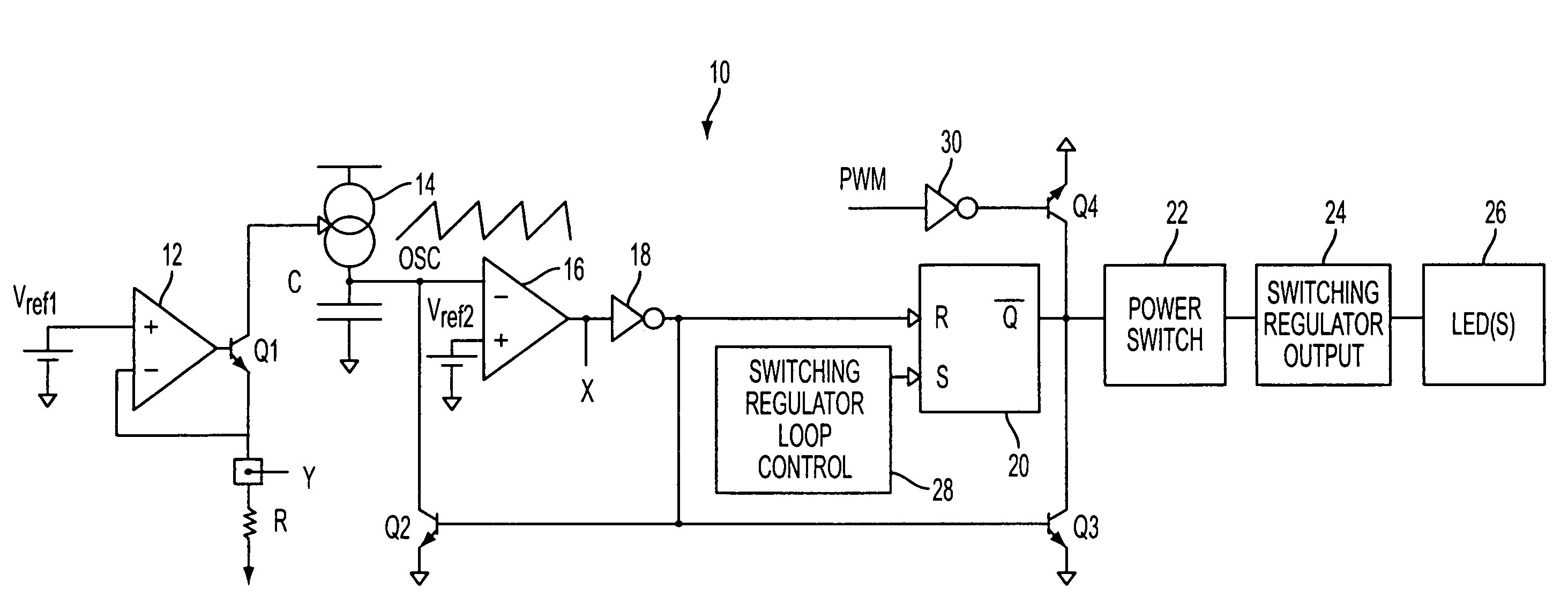
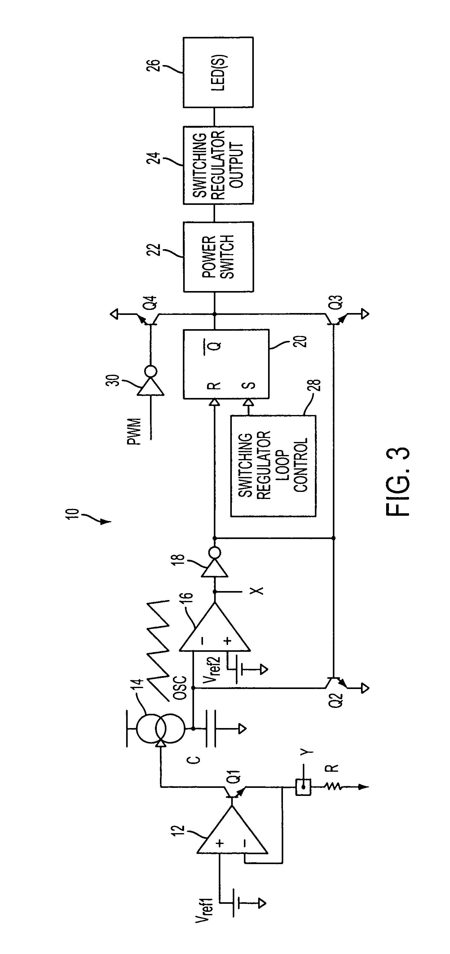
[0031]The present disclosure will be made with the example of a LED driving circuit 10 shown in FIG. 3. It will become apparent, however, that the concepts described herein are applicable to any LED driver having a LED dimming control mechanism.

[0032]The LED driving circuit LED 10 may be provided on a chip having an input auxiliary circuit for supporting external LED dimming control. The input auxiliary circuit may include an operational amplifier 12 arranged in a negative feedback loop. A non-inverting input of the amplifier 12 is supplied with a reference voltage Vref1, while an inverting input is connected to a node Y. As discussed in more detail later, the node Y (if made external to the LED driving circuit) may be controlled by an external circuit in order to synchronize PWM active edge to the start of a new oscillator cycle. The output of the operational amplifier 12 drives the base of a bipolar transistor Q1 so as to create a voltage at the node Y connected to the emitter of ...


PUM


Abstract

Circuitry and methodology for providing LED dimming control in a LED driving system having a switching regulator for providing power supply to drive the LED. The switching regulator includes a switching circuit to which an oscillation signal is applied to control switching of the switching circuit. A dimming control input is supplied with a pulse-width modulation (PWM) dimming control signal to provide PWM dimming control of the LED. The dimming control input applies the PWM dimming control signal to control switching of the switching circuit. A synchronizing circuit is provided for synchronizing the oscillation signal to the PWM dimming control signal.

Description

TECHNICAL FIELD[0001]This disclosure relates to power supply systems, and more particularly, to light-emitting diode (LED) dimming control circuitry and methodology that allows a LED driver to increase the maximum pulse-width modulation (PWM) dimming ratio and avoid LED flicker.BACKGROUND ART[0002]LED dimming control may be utilized to provide control of LED brightness without changing LED color. For example, PWM dimming control uses a PWM signal to drive a LED. FIG. 1 illustrates the PWM dimming control signal, as well as inductor current in the LED driver and LED current controlled by the PWM input signal. The LED current may be programmed for maximum brightness and then “chopped” over a range of duty cycles to achieve a range of brightness levels. The PWM dimming control signal may be applied to the LED through a field effect transistor. When the PWM signal goes low, the LED may be turned off. When the PWM signal goes high, the LED current may return to its previous on state.[000...

Claims


Application Information

Patent Timeline
Patent Type & Authority Patents(United States)
IPC IPC(8): H05B41/16H05B44/00
CPCH05B33/0815Y02B20/346Y10S315/04Y02B20/30H05B45/3725
Inventor MAROSEK, MARK W.
Owner ANALOG DEVICES INT UNLTD
Why Eureka
Try Eureka