Method for calculating power capability of battery packs using advanced cell model predictive techniques

a cell model and power capability technology, applied in the field of battery charge power and discharge power estimation, can solve the problems of inefficient battery use, inconvenient use, and limited prior art charge calculation methods in several respects

Active Publication Date: 2008-01-22
LG ENERGY SOLUTION LTD
View PDF6 Cites 89 Cited by
  • Summary
  • Abstract
  • Description
  • Claims
  • Application Information

AI Technical Summary

Benefits of technology

[0021]Methods of the present invention improve upon prior art estimation of power based on voltage limits. In the present invention, voltage limits are used to calculate the maximum charge / discharge current in a way that includes a user-defined time horizon Δt. Two primary cell model embodiments are in the present invention for the calculation of maximum charge / discharge power based on voltage limits. The first is a simple cell model that uses a Taylor-series expansion to linearize the equation involved. The second is a more complex and accurate cell model that models cell dynamics in discrete-time state-space form. The cell model can incorporate a variety of inputs such as temperature, resistance, capacity, etc. One advantage of using model-based approach is that the same cell model may be used in both Kalman filtering to produce the SOC and the estimation of maximum charge / discharge current based on voltage limits.

Problems solved by technology

This prior art charge calculation method is limited in several respects.
More importantly, the cell model used is too primitive to give precise results.
Overly optimistic or pessimistic values could be generated, either posing a safety or battery-health hazard or causing inefficient battery use.

Method used


Image

  • Method for calculating power capability of battery packs using advanced cell model predictive techniques
  • Method for calculating power capability of battery packs using advanced cell model predictive techniques
  • Method for calculating power capability of battery packs using advanced cell model predictive techniques

Examples


Embodiment Construction

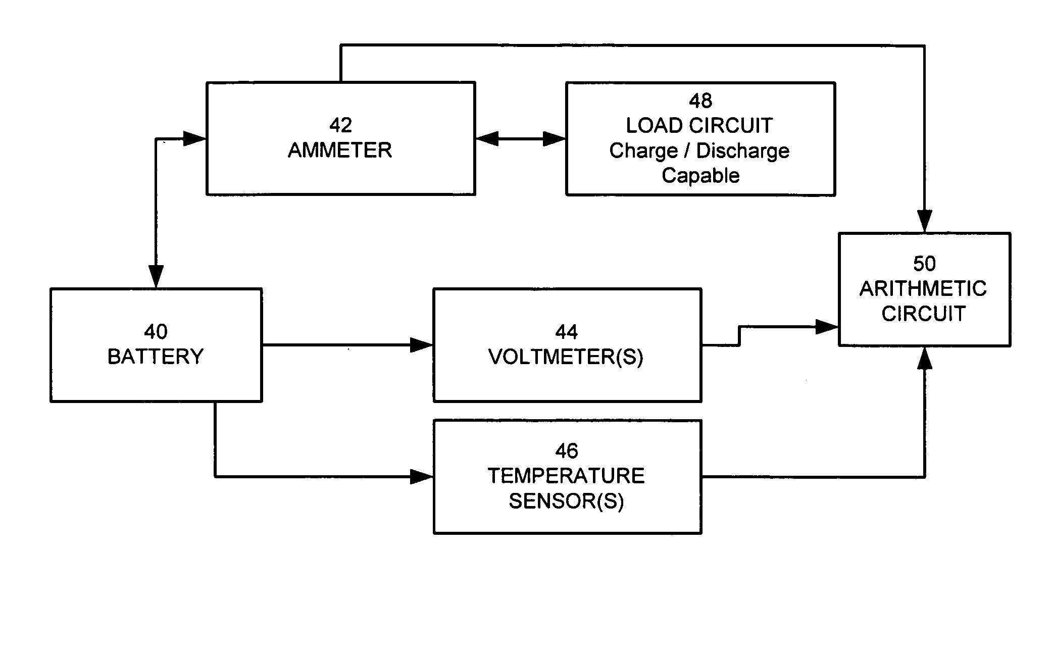
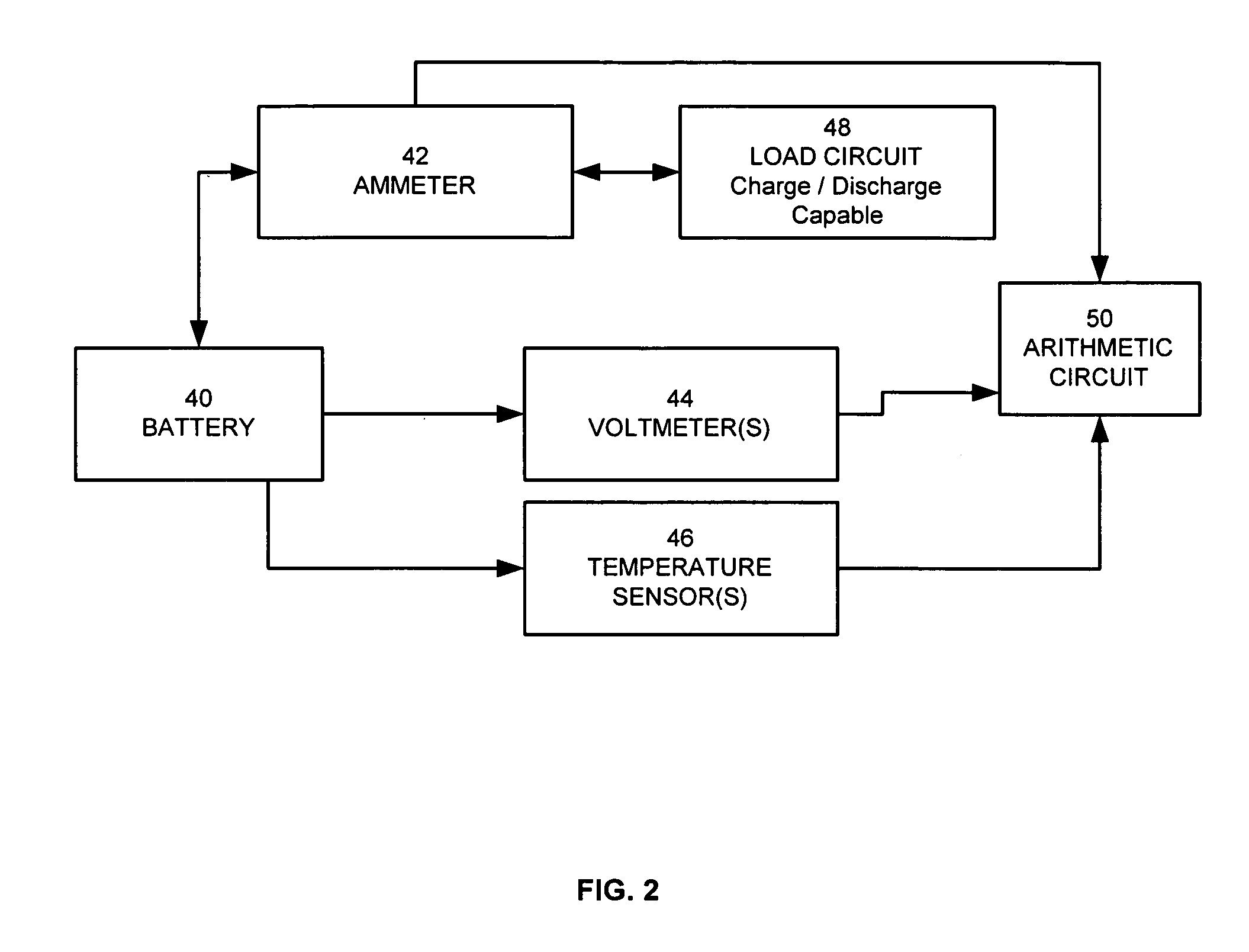
[0038]Embodiments of the present invention relate to battery charge estimation for any battery-powered application. In one embodiment, the estimator method and apparatus find the maximum absolute battery charge and / or discharge power (based on present battery pack conditions) that may be maintained for Δt seconds without violating pre-set limits on cell voltage, state-of-charge, power, or current.

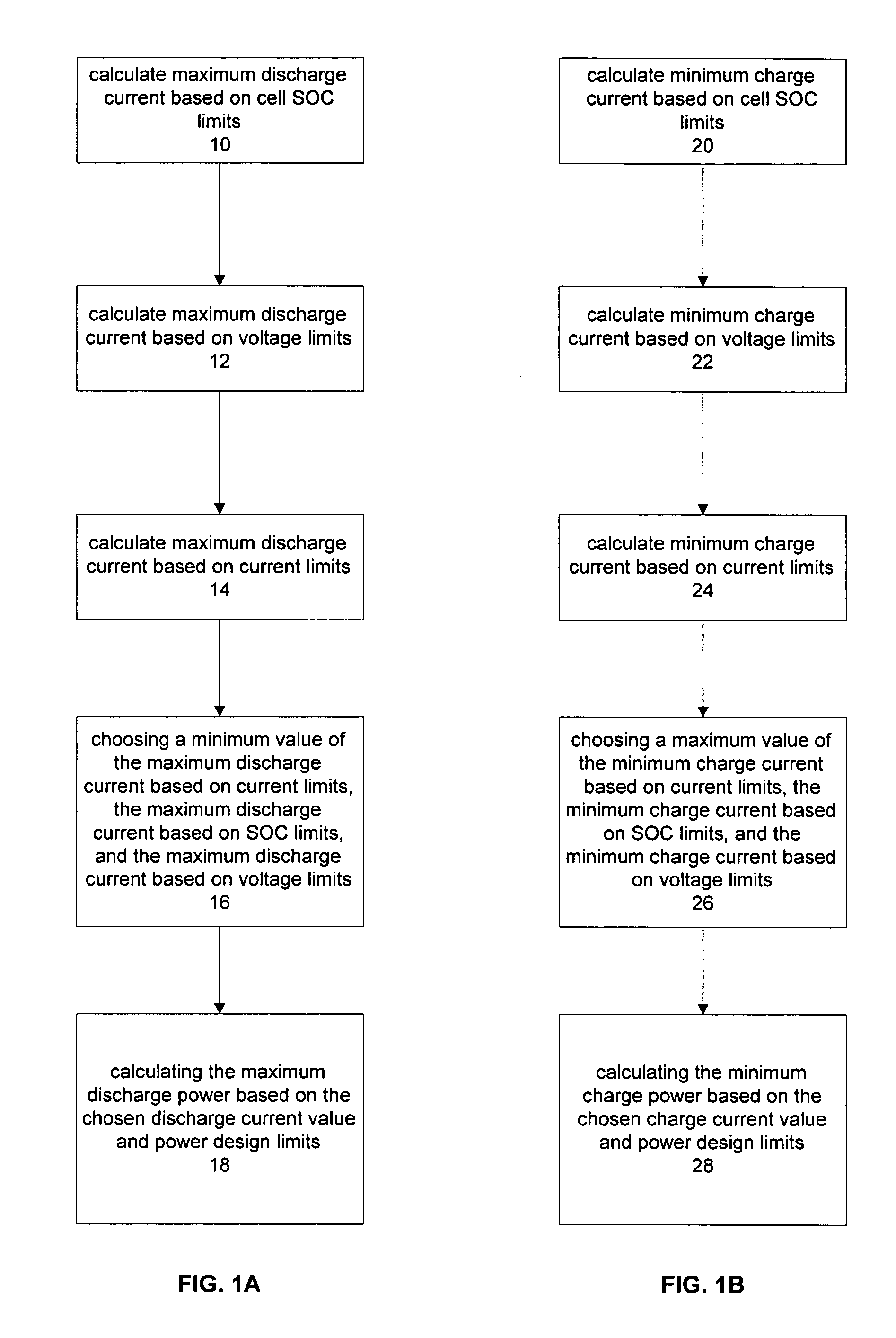
[0039]FIGS. 1A and 1B illustrate an overview of the embodiments of the present invention. FIG. 1A shows a method for finding the maximum discharge power for a user-defined time horizon Δt, i.e. how much power may be drawn from the battery continuously for use for the next Δt time period. In vehicle applications, accurate estimation of maximum discharge power can help prevent the hazardous occurrence of over-drawing the battery.

[0040]In step 10, the maximum discharge current is calculated based on pre-set limits on state-of-charge. The estimation explicitly includes a user-defined time horiz...


PUM

PropertyMeasurementUnit
discharge currentaaaaaaaaaa
charge currentsaaaaaaaaaa
constant currentaaaaaaaaaa

Abstract

The present invention relates to a method and an apparatus for estimating discharge and charge power of battery applications, including battery packs used in Hybrid Electric Vehicles (HEV) and Electric Vehicles (EV). One charge / discharge power estimating method incorporates voltage, state-of-charge (SOC), power, and current design constraints and works for a user-specified prediction time horizon Δt. At least two cell models are used in calculating maximum charge / discharge power based on voltage limits. The first is a simple cell model that uses a Taylor-series expansion to linearize the equation involved. The second is a more complex and accurate model that models cell dynamics in discrete-time state-space form. The cell model can incorporate a inputs such as temperature, resistance, capacity, etc. One advantage of using model-based approach is that the same model may be used in both Kalman-filtering to produce the SOC and the estimation of maximum charge / discharge current based on voltage limits.

Description

[0001]This application claims the benefit of U.S. Provisional Patent Application No. 60 / 524,326, filed on Nov. 20, 2003, the disclosure of which is hereby incorporated by reference.[0002]Portions of the disclosure of this patent document contain material that is subject to copyright protection. The copyright owner has no objection to the facsimile reproduction by anyone of the patent document or the patent disclosure as it appears in the Patent and Trademark Office file or records, but otherwise reserves all copyright rights whatsoever.BACKGROUND OF THE INVENTION[0003]1. Field of the Invention[0004]The present invention relates to the implementation of a method and apparatus for estimating battery charge power and discharge power.[0005]2. Background Art[0006]A number of high-performance battery applications require precise real-time estimates of the power available to be sourced by the battery pack. For example, in Hybrid Electric. Vehicles (HEVs) and Battery Electric Vehicles (BEVs...

Claims


Application Information

Patent Timeline
Patent Type & Authority Patents(United States)
IPC IPC(8): H02J7/00H02J7/16G01N27/416G01R31/36
CPCG01R31/3648G01R31/367G01R31/374G01R31/3828H02J7/00G01R31/36
Inventor PLETT, GREGORY L.
Owner LG ENERGY SOLUTION LTD
Why Eureka
Try Eureka