
Surgical lighting control and video system

a technology of video system and control panel, applied in the field of surgical lighting, table and accessory arts, can solve the problems of inability to monitor the power delivered to the bulbs within the lighthead, and inability to control the camera personnel, etc., to achieve the effect of simple and intuitive control of the system

Active Publication Date: 2008-01-22
AMERICAN STERILIZER CO
View PDF11 Cites 22 Cited by
  • Summary
  • Abstract
  • Description
  • Claims
  • Application Information

AI Technical Summary

Benefits of technology

[0008]The preferred embodiments of the present invention provide a plug and play control interface that gives a user access to multiple devices at one station, gives the surgeon control of more devices within the sterile field, and makes control of the system simpler and more intuitive.
[0009]The present invention improves user access to the system by providing a graphical LCD display for use to control a plurality of devices, such as overhead lighting, ambient lighting, cameras, and other operating room accessories. The surgeon's control is improved by a voice interface system, allowing the surgeon to adjust lighting and other aspects by simply speaking. A foot pedal interface and an infra-red remote control interface grant the surgeon control of the cameras, enabling direct control of rotate and zoom functions of the camera.
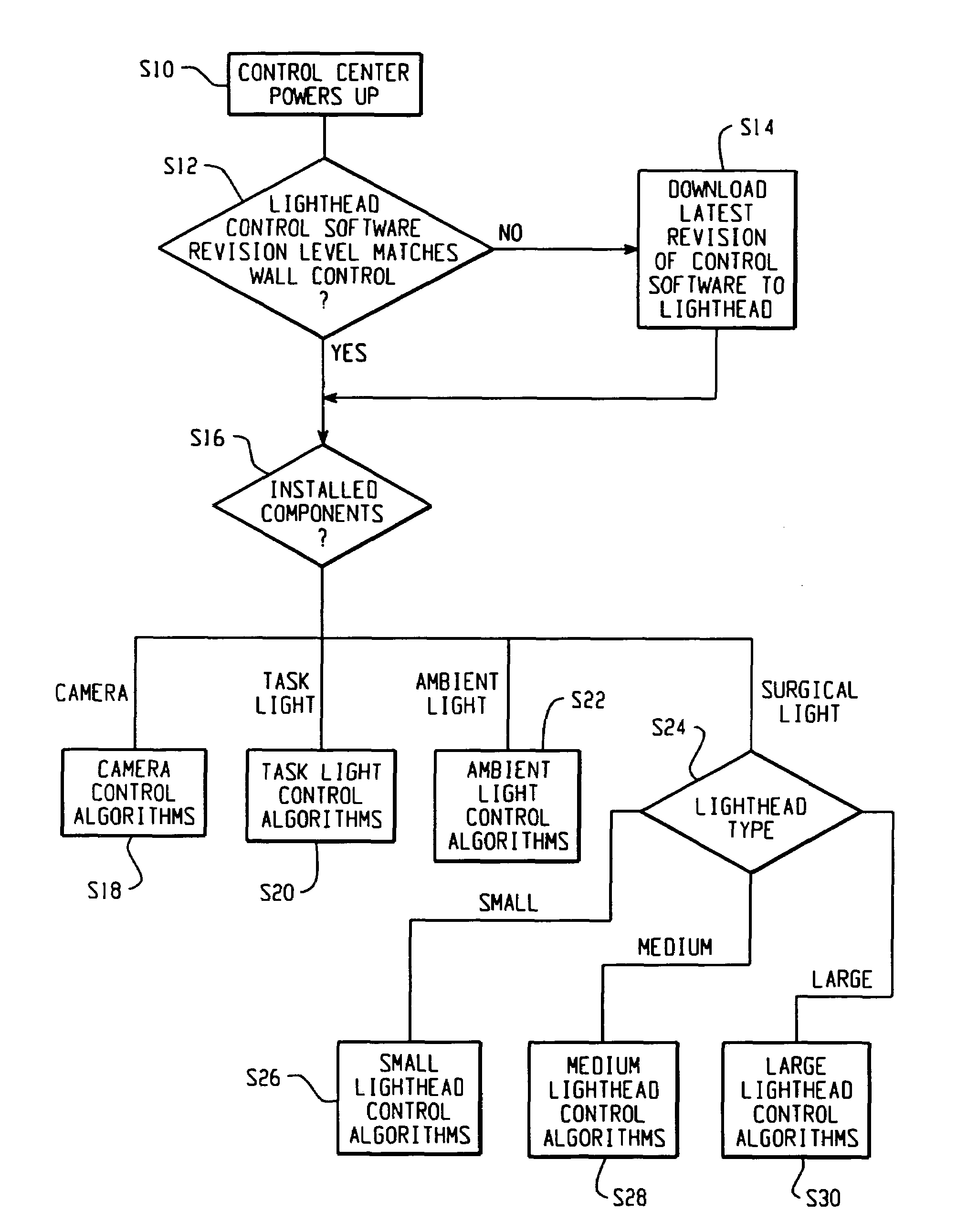
[0010]The preferred embodiments of the present invention provide plug and play compatibility, so that devices such as cameras, entire lightheads, task lights, and other surgical accessories can be switched in and out of the system as needed, without the need to update system software or control protocol. This may occur as additional lightheads or other devices are added to the system or when devices are replaced as by way of an upgrade or the like.

Problems solved by technology

Some systems offer no control of the camera to personnel in the OR.
Without physically moving the camera / lighthead, such systems only offer a single camera orientation and zoom factor.
Existing systems do not monitor power delivered to the bulbs within the lighthead.
This results in light intensity fluctuations due to bulb deviations, voltage fluctuations, and line resistences.
Variances in the lamp power can reduce light intensity with potential adverse effects on the surgical procedure or increase light intensity causing a reduced lamp life.
Additionally, most existing systems do not offer centralized control.
This leads to confusion when operating the systems, and clutter in the OR due to additional user interface locations.
In systems using a centralized control, hardware updates / upgrades are difficult because the software of the control often cannot be adapted to recognize and operate with the new equipment.

Method used


Image

  • Surgical lighting control and video system
  • Surgical lighting control and video system
  • Surgical lighting control and video system

Examples


Embodiment Construction

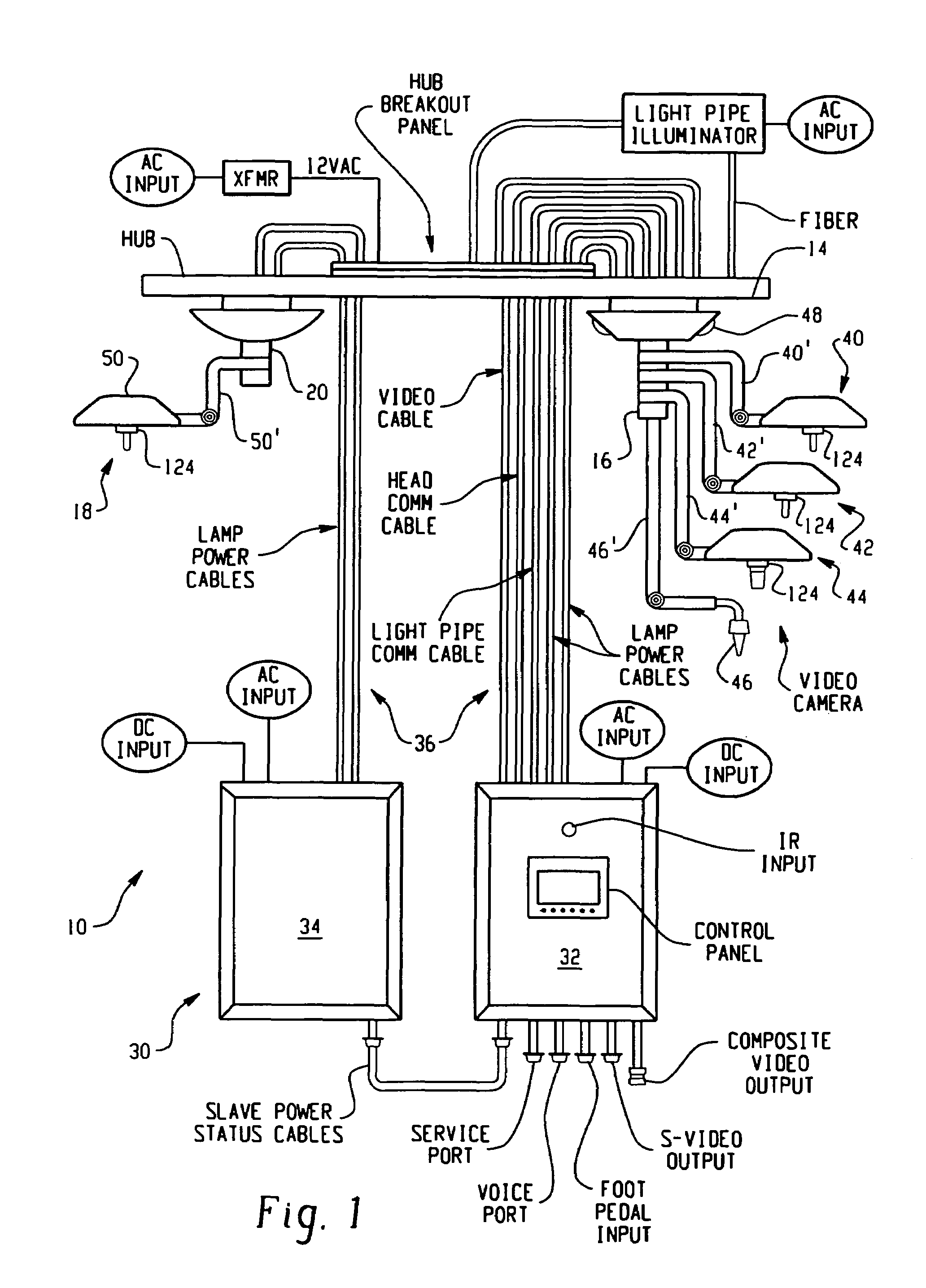
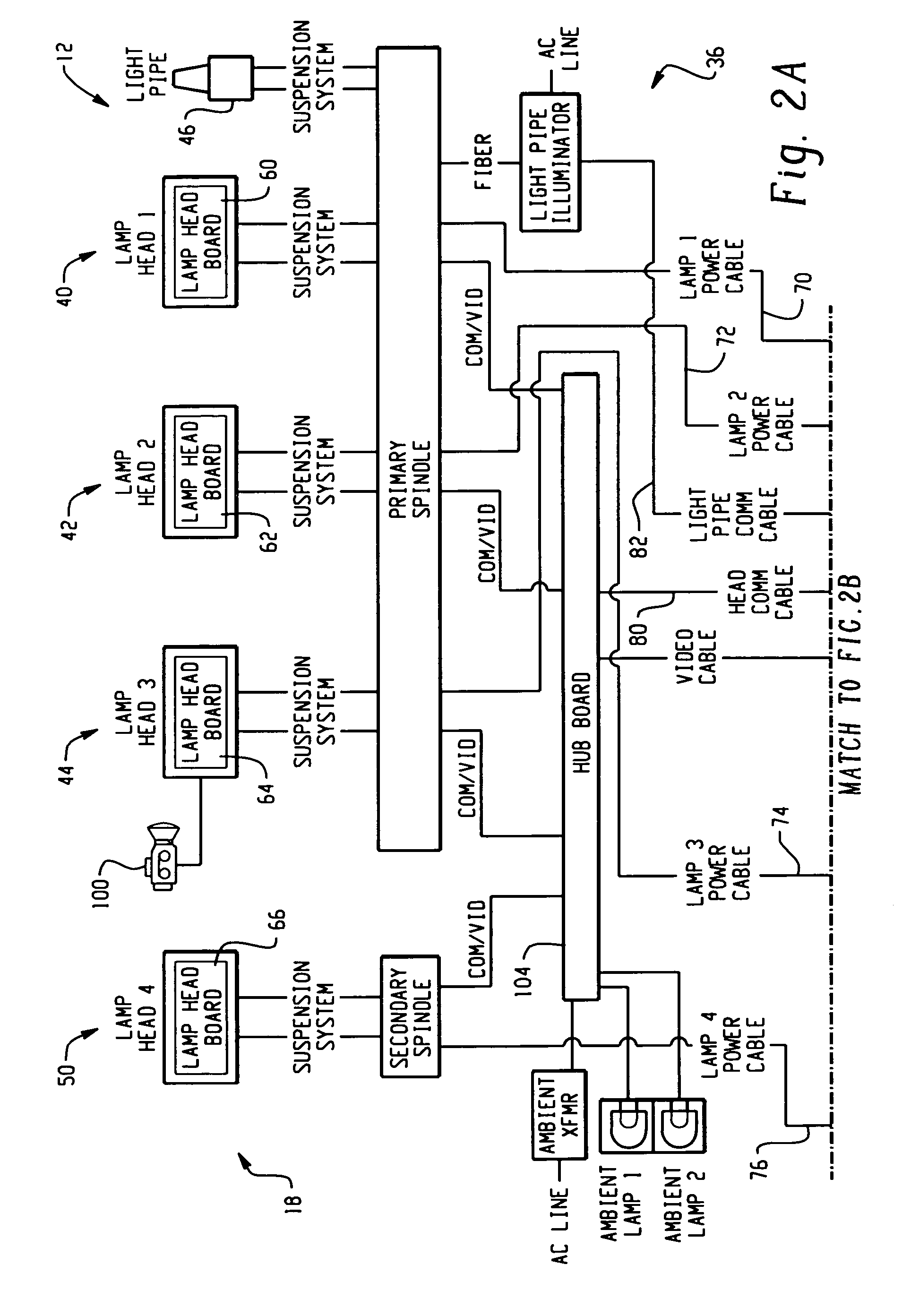
[0029]With reference now to the drawing figures wherein the showings are purposes of illustrating the preferred embodiments of the invention only and not for purposes of limiting same, FIG. 1 shows a surgical lighting system 10 including a first set of lighting devices 12 supported from the ceiling 14 of an operating room by a primary spindle hub 16 and a second set of lighting devices 18 supported at the ceiling 14 by a secondary spindle hub 20. A lighting control apparatus 30 includes a master control unit 32 for operating the first set of lighting devices 12 and a second control unit 34 for controlling operation of the second set of lighting devices 18. A set of communication and power lines 36 connect the lighting control apparatus 30 with the first and second set of lighting devices 12, 18 for control thereof in a manner to be described in greater detail below.

[0030]The first set of lighting devices 12 supported by the primary spindle hub 16 includes three (3) overhead lighthea...


PUM


Abstract

A surgical light system (10) includes a lighthead (44) coupled to a suspension arm (41′) adapted for mounting to a surface (14) of a surgical room. A bulb (130) is disposed in the lighthead. A processor (120) in the lighthead is operatively coupled with the bulb for controlling an intensity of light of the bulb and is adapted to generate a lighthead status signal representative of a first status of the lighthead. A control apparatus (32, 34) is in operative communication with the processor (120) in the lighthead. The control apparatus receives the lighthead status signal and selects a set of control algorithms from among a group of algorithms based on the lighthead status signal for controlling the lighthead. The lighthead status signal includes information regarding a size of the lighthead, an intensity of light from the bulb, a condition of the bulb, a level of current applied to the bulb, a level of current applied to the bulb, a level of voltage applied to the bulb, an internal temperature of the lighthead, and the presence of one or more of a video camera, a surgical task light, and a controllable ambient light. A human-readable display device (160) is provided for displaying information relating to the lighthead status signal. Several levels of redundancy are provided in the control system to minimize the potential loss of control due to failures. In that regard, the lightheads are operable when the control apparatus (32, 34) fails.

Description

CROSS-REFERENCE TO RELATED APPLICATION[0001]This application claims the benefit of U.S. provisional application Ser. No. 60 / 348,999, filed Jan. 15, 2002.BACKGROUND OF THE INVENTION[0002]The present invention relates to the surgical lighting, table, and accessory arts, and, more particularly, to a surgical lighting control system providing multiple user interfaces, centralized graphical control for various functions, advanced camera detection / signal routing, and closed loop control of lamp intensity. It finds particular application in conjunction with providing a comprehensive control system for a surgical operating room (OR) theater and will be described with particular reference thereto. It is to be appreciated, however, that the invention also finds application in other multi-task control applications and is not limited to the aforementioned operating room environment.[0003]Typically, in an operating room setting, large, high lumen output lightheads are used to illuminate the surg...

Claims


Application Information

Patent Timeline
IPC IPC(8): H04N7/18A61B17/00A61B19/00F21S8/00
CPCA61B19/52H04N5/23216A61B19/5202A61B19/5212Y10S362/804F21W2131/205A61B2017/00199A61B90/36A61B90/30A61B90/361H04N23/62Y02B20/40H04N7/18
Inventor RUS, STEVEN H.DRABINSKI, TERRY A.PETRUCCI, JAMES A.JESURUN, DAVIDGRESZLER, ALAN J.KESELMAN, YURY
Owner AMERICAN STERILIZER CO
Learn More