Self-locking bone screw and implant

a bone screw and implant technology, applied in the field of self-locking bone screw and implant, can solve the problems of screw backwards from the implant, screw may not be able to fully lock, and project beyond the top surface of the implant into a sensitive biological environmen

Active Publication Date: 2008-01-29
ZIMMER BIOMET SPINE INC
View PDF45 Cites 110 Cited by
  • Summary
  • Abstract
  • Description
  • Claims
  • Application Information

AI Technical Summary

Benefits of technology

[0007]The present invention relates to an orthopedic implant having an internally threaded recess that receives the external threads of a screw that fastens the implant to a bone portion. The screw has external threads that form two distinct areas or sections of thread along the longitudinal length of the screw wherein the thread has a different cross section for each of the areas. The first area is a bone engaging area which has ...

Problems solved by technology

One problem that may be encountered with implants that are fastened to the bone using a screw is that there may be too much play between the screw and the implant, or that the screw may back out of the implant.
If a screw backs out of an implant depending on the placement there may be a risk that it may project beyond the top surface of the implant into a sensitive biological area.
This raises the possibility of irritation to adjoining soft tissue.
Another possibility if there is too much movement between the plate and the screw is that the plate may play against the screw and increase the risk of shearing the screw.
However, the existence of multiple start threads can caus...

Method used


Image

  • Self-locking bone screw and implant
  • Self-locking bone screw and implant
  • Self-locking bone screw and implant

Examples


Embodiment Construction

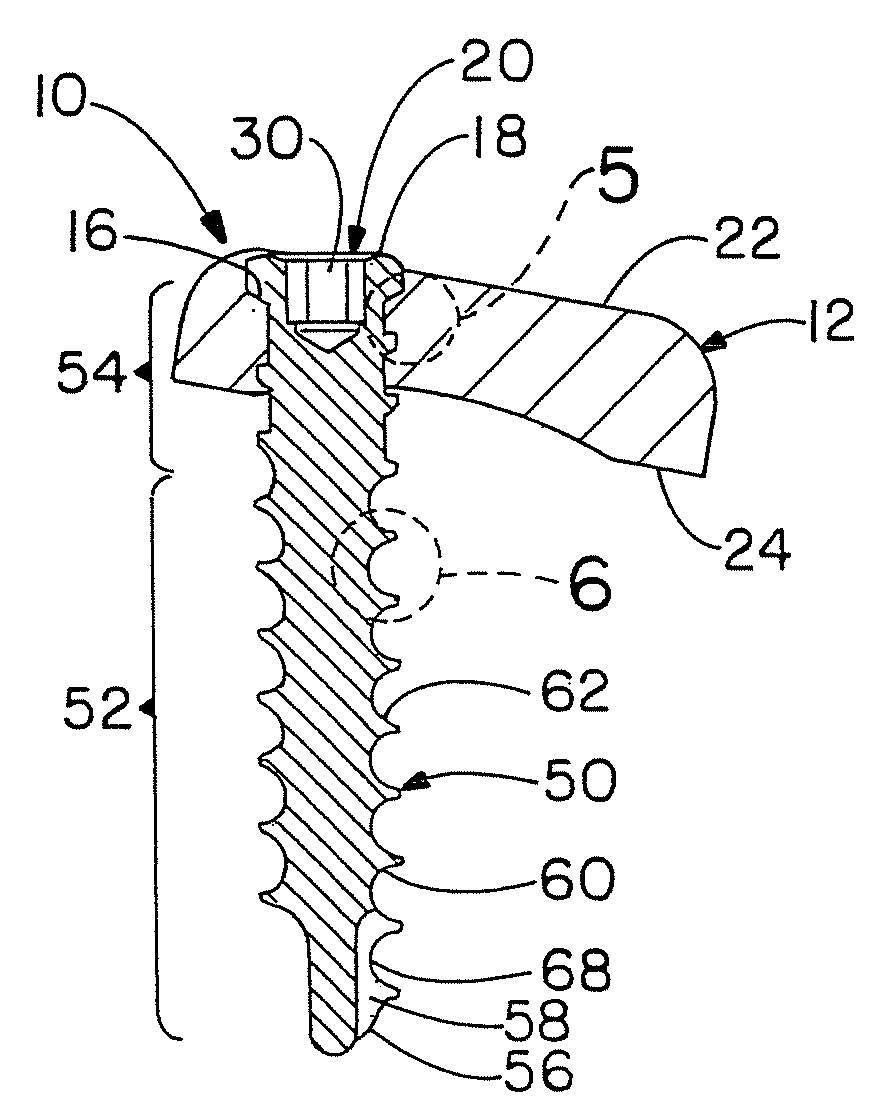
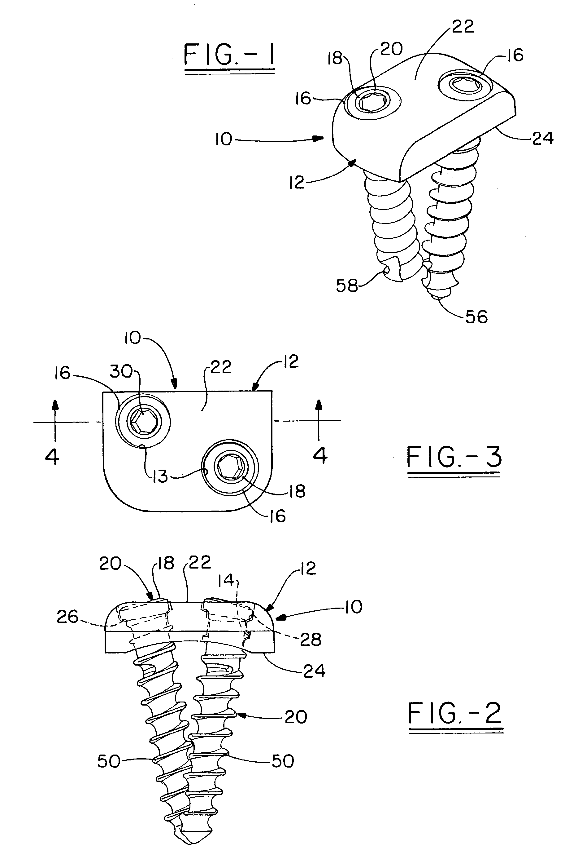
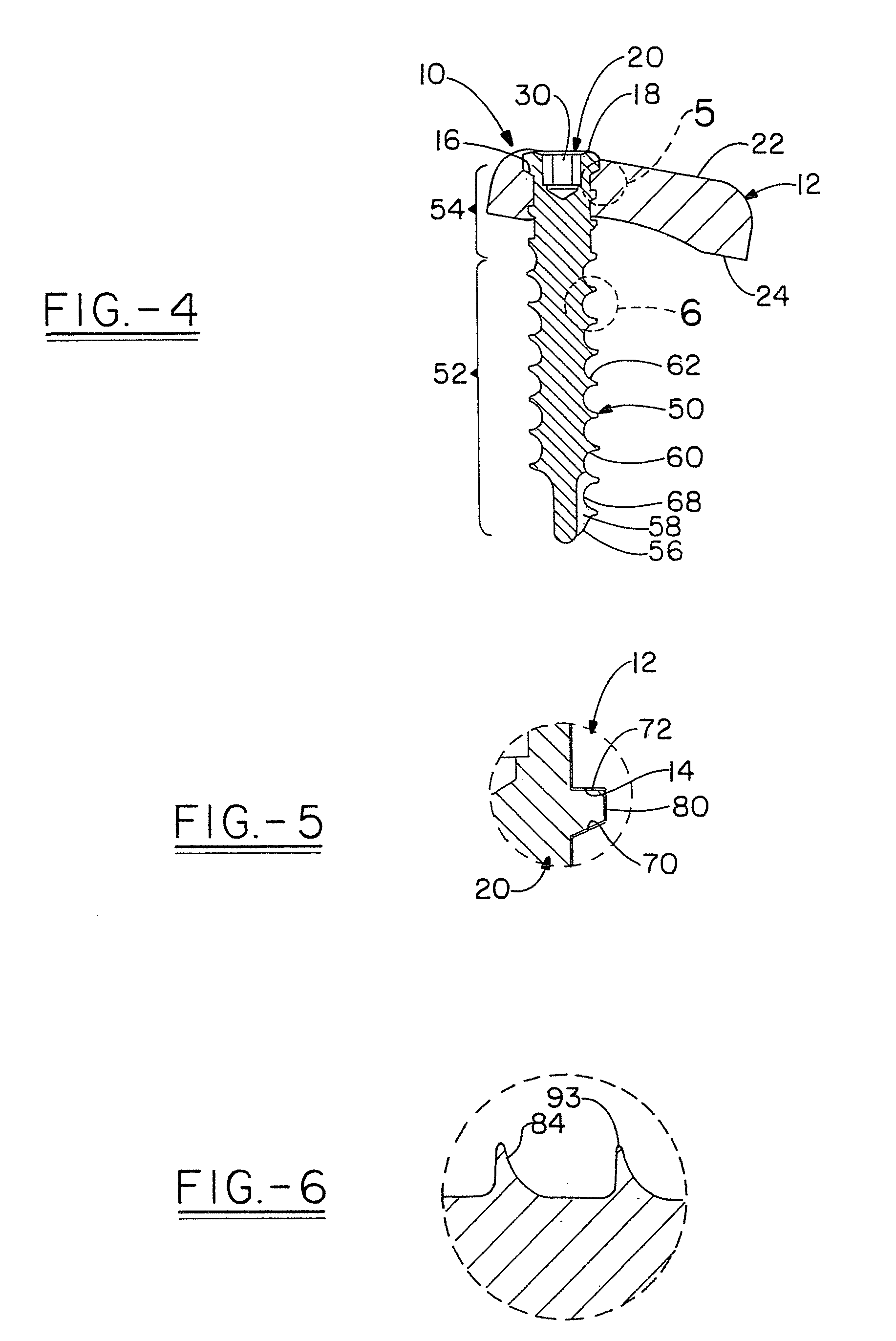
[0019]The present invention relates to an orthopedic implant assembly shown generally at 10 and including an implant 12 having at least one through bore 13 which includes internal or female threads 14. The bore 13 has an opening at the top with a countersunk area 16 which is configured so that the circular head 18 of a corresponding screw 20 will be mostly recessed within the bore 13 and will have only minimal projection beyond the top surface 22 of the implant surrounding the opening. In addition, the head 18 has a rounded top surface to help accomplish this goal. In addition, the implant 12 is shown as having two opposing surfaces (i.e. top 22 and bottom 24 relative to the bone surface) defining a thickness between. The bottom surface 24 is shown in this case, as having a curve to better fit the corresponding bone engaging surface. Further, the head 18 has a bottom bevel 26 that rest against a beveled recess 28 in the countersunk area 16 so as to secure the screw 20 in place. Also...


PUM


Abstract

An orthopedic implant assembly is presented which has a flange member having a through bore with internal threads and a screw which has a single continuous thread that has a first section and a second section. The cross sectional configuration of the thread in the first section is different than the cross sectional configuration in the second section. The first section defines a cancellous thread while the second section defines a locking .thread which is an asymmetrical buttress thread that has the same pitch and angle along the leading or thrust surface as the cancellous thread and a thicker square spiral edge or face joined to a transverse rear surface.

Description

[0001]This Patent Application is Based Upon U.S. Provisional Application Ser. No., 60 / 356,395, Filed Feb. 12, 2002[0002]The present invention relates to an orthopedic implant and a mating bone screw which locks in position in a threaded through bore in the implant. In particular, the screw has a continuous thread having a leading surface that has one constant pitch throughout the length of the screw. However the single thread has two sections each having their own thread configuration. From the tip end the first area of thread comprises a cancellous screw thread which is designed for engagement of the bone whereas the second, shorter area near the distil end is modified to form the locking thread having the same angle as for the first section of thread on the leading edge or thrust surface, but having a different angle than the first section on the rear surface. The locking thread also has a truncated peripheral edge as compared to the first thread section to define a thicker spiral...

Claims


Application Information

Patent Timeline
IPC IPC(8): A61B17/58A61B17/70A61B17/80
CPCA61B17/8057A61B17/7059
Inventor HARRIS, PETER M.
Owner ZIMMER BIOMET SPINE INC
Why Eureka
Try Eureka