Conversion of model components into references

a technology of model components and references, applied in the field of conversion of model components into references, can solve problems such as execution errors, general suitability for describing dynamic system behavior, and disallow the use of blocks

Active Publication Date: 2008-01-29
THE MATHWORKS INC
View PDF10 Cites 70 Cited by
  • Summary
  • Abstract
  • Description
  • Claims
  • Application Information

AI Technical Summary

Problems solved by technology

Such systems range from simple to highly complex systems.
For instance, flow-charts are block diagrams used to capture process flow and are not generally suitable for describing dynamic system behavior.
A restrictive flag disallows the use of blocks in certain modeling contexts.
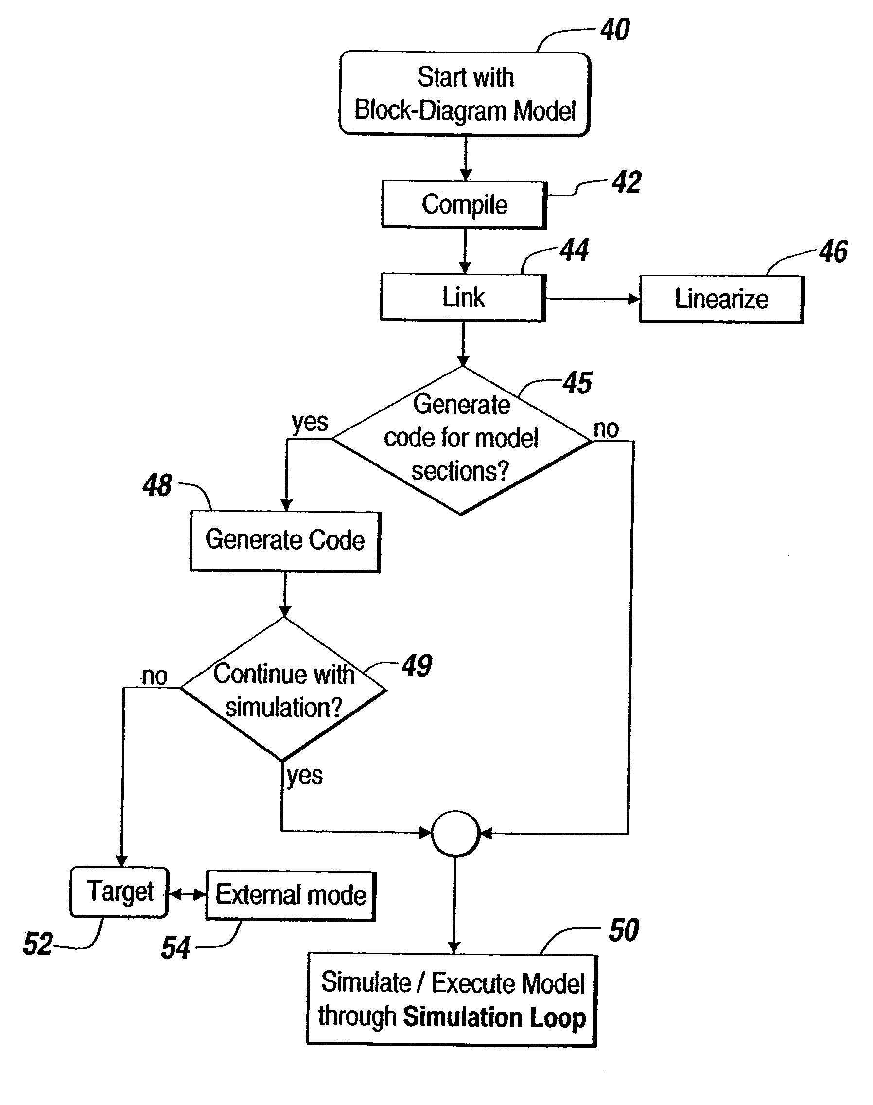
If there are any unresolved parameters, execution errors are thrown at this point.
If not, an error is issued.
For instance, if an Integrator block is implemented to only accept numbers of double precision datatype, then this block will error out if it is driven by a block that produces single precision data, unless the user has asked for an implicit data conversion.
Attempting to correlate data dependencies directly to the signals found within a block diagram is incorrect and leads to the conclusion that Simulink® does not satisfy data dependencies, i.e., the execution of the operations or block methods does not satisfy data dependencies if one interprets signal connectivity as specifying data dependencies.
It should be noted that the traceability associated with interpretive execution comes at the price of increased overhead in the form of additional execution-related data-structures and messaging in the engine.
Such bugs prove much more expensive to track and fix once the system has been implemented in hardware.
Additionally, the use of rate transition blocks restricts the connection of blocks with different rates.
Otherwise, the outputs of the model could lead to false conclusions about the behavior of the system under investigation.
This might lead an investigator to false conclusions about the physics of the bouncing ball.
In the case of Fixed-step solvers, there is no notion of zero-crossing detection and one is not guaranteed to find all points of discontinuity.
While it is theoretically possible to have Variable-step solvers in the context of multitasking, such a combination is not employed in practice.
This is because the step-size for such solvers can become very small making it impossible to keep up with the real-time constraint that generally goes along with multitasking execution.
An added complication is that the integration step in such solvers is iterative and takes varying amounts of time at each step of the execution.
Additionally, they are not usually employed in systems that need to operate in real-time.
Conventional simulation models become more complex as models are developed that model more complex systems.
In fact, including arbitrary detail often complicates and slows the design, analysis, and / or synthesis tasks.
The discrete event controller may be designed based on the assumption that the driver commands can be either “up”, “down”, or “neutral”, but in an actual implementation there may be no guarantee that these commands are mutually exclusive when provided to the discrete event controller.
However, state-of-the-art tools require this partitioning to be a manual process.
As such, the process for seeking out opportunities for replacing subsystems with references suffers from the well-known drawbacks of manual implementations, including human error, incomplete analysis, and inability of a user to grasp the full complexity of a highly complex system model.
The process for selecting the size of each partition is difficult in general.
This, however, may result in a large number of repeated patterns that is very similar to the potential copy / paste use of model designers.
However, when the design moves toward an implementation, the automatically synthesized code may be devoid of such polymorph properties, and therefore, the actual implementation may require fixed data types.
In particular, if sophisticated algorithms of a scaleable complexity are designed (e.g., linear or quadratic) then automated methods may perform better than a manual approach, because humans do not scale well, even for algorithms with low order of complexity.

Method used


Image

  • Conversion of model components into references
  • Conversion of model components into references
  • Conversion of model components into references

Examples


Embodiment Construction

[0198]An illustrative embodiment of the present invention relates to an automated model simplification feature that systematically converts duplicate or otherwise selected patterns in a model into references. The invention enables the use of multiple references to one unit that contains the otherwise duplicated, or selected, functionality. Duplicated functionality is identified based on a number of arguments that may be user supplied. These arguments include the level of polymorphism (e.g., which of the sample times, dimensions, and data types can be propagated in) but also the maximum size of the patterns to look for to address the general trade-off of generating few partitions with many blocks or many partitions with few blocks and which modeling constructs are used (e.g., whether Go To / From connections such as in Simulink® are present). The present invention also facilitates converting the model into potentially disjoint partitions. When changes to the model are made, these chang...


PUM


Abstract

An automated model componentization feature systematically converts duplicate or otherwise amenable patterns in a model into references. Multiple references are simplified to one unit that contains the otherwise duplicated functionality. Duplicated or selected functionality is identified based on a number of arguments that may be user supplied. These arguments include the level of polymorphism (i.e., which of the sample times, dimensions, and data types can be propagated in) but also the maximum size of the patterns to look for to address the general trade-off of generating few partitions with many blocks or many partitions with few blocks and which modeling constructs are used (e.g., whether Go To/From connections such as in Simulink® are present). Model conversions can result in potentially disjoint partitions.

Description

FIELD OF THE INVENTION[0001]The present invention relates to a system and method suitable for altering entity relationship models, and more particularly to an automated feature for systematically converting duplicate, or otherwise selected, patterns of model components into references to individual model components.BACKGROUND OF THE INVENTION[0002]Various classes of graphical models describe computations that can be performed on computational hardware, such as a computer, microcontroller, FPGA, and custom hardware. Classes of such graphical models include time-based block diagrams, such as those found within Simulink®, from The MathWorks, Inc. of Natick, Mass., state-based and flow diagrams, such as those found within Stateflow®, from The MathWorks, Inc. of Natick, Massachusetts, data-flow diagrams, circuit diagrams, and software diagrams, such as those found in the Unified Modeling Language. A common characteristic among these various forms of graphical models is that they define s...

Claims


Application Information

Patent Timeline
Patent Type & Authority Patents(United States)
IPC IPC(8): G06F17/50
CPCG06F17/50G06F17/504G06F30/00G06F30/3323
Inventor WARLOCK, ARWEN
Owner THE MATHWORKS INC
Why Eureka
Try Eureka