

Method and equipment for drying a pulp web using hot air of different temperatures
- Summary
- Abstract
- Description
- Claims
- Application Information
AI Technical Summary
Benefits of technology
Problems solved by technology
Method used
Image

Examples
Embodiment Construction
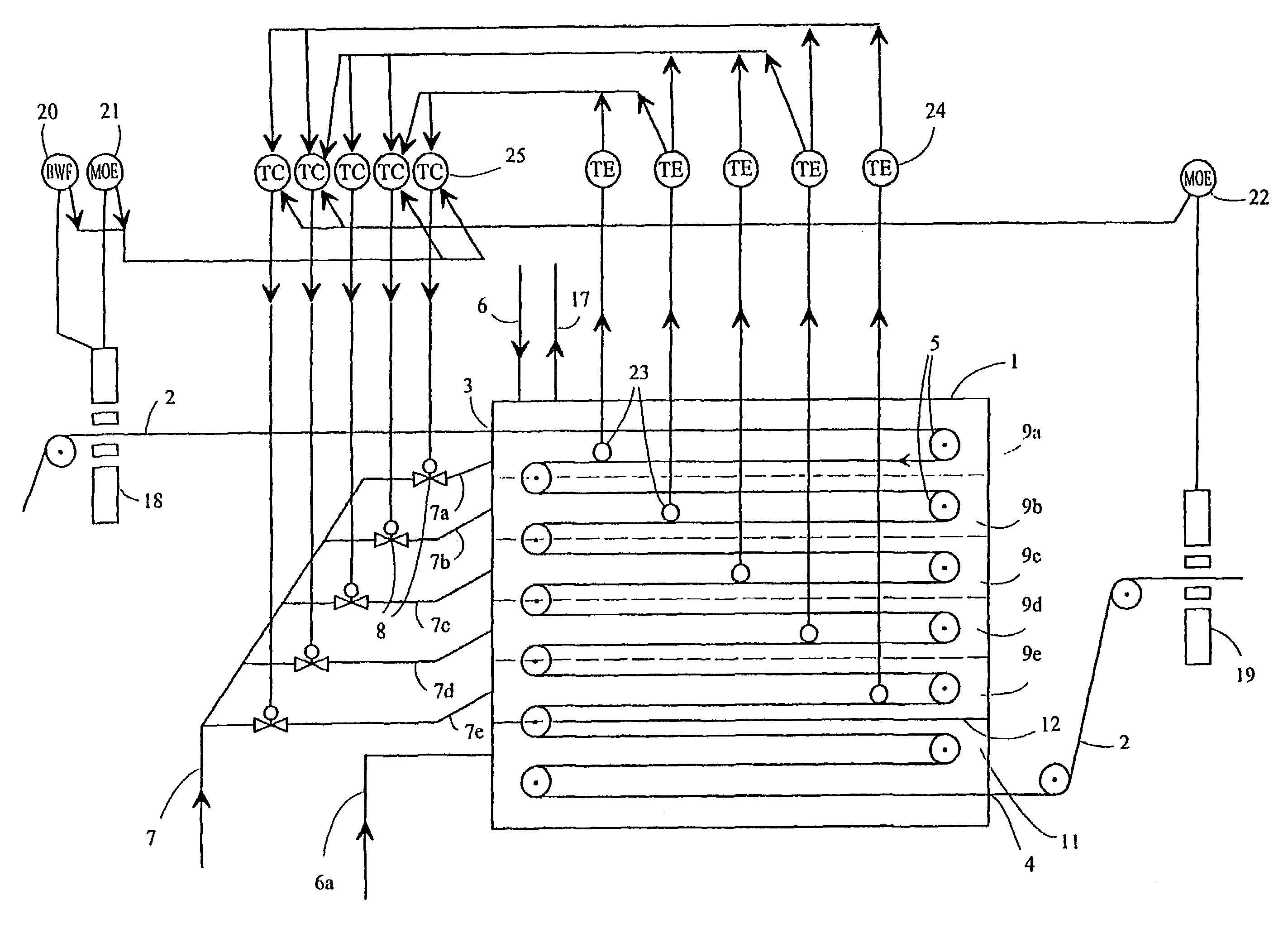
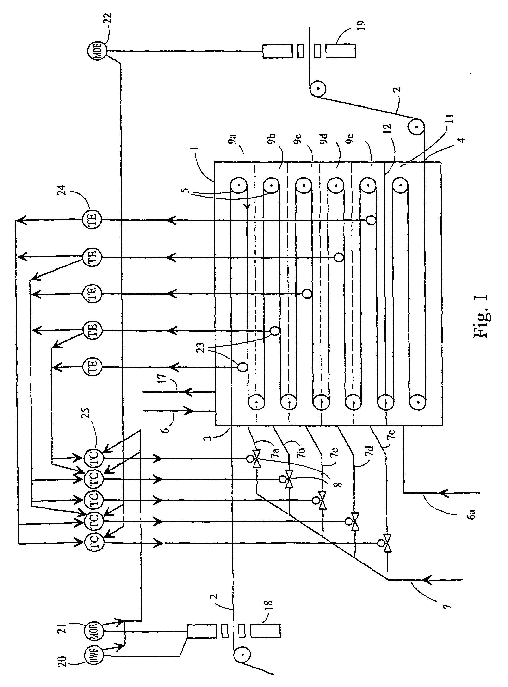
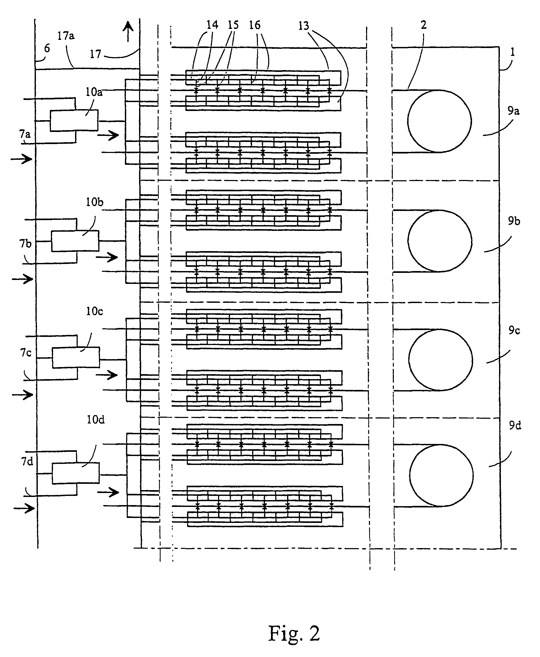
[0006]The purpose of the invention is to provide a solution that eliminates the problems described above, enabling controlled drying of the pulp web even at the high velocities of current drying machines. The invention is characterized in that the drying box used for drying the web comprises drying zones, into which the air is blown independently so that the web is dried in the various zones at different temperatures.
[0007]In present drying processes, wherein drying in the drying box is effected at the same temperature from beginning to end, the drying process is not optimal, because the drying temperature in the drying box is determined by the evaporation in the initial part of the box, which is effected so as not to harm the web. The middle part of the box, which would allow a higher temperature and more effective evaporation, cannot be utilized; therefore, the efficiency is poor. The middle part is the longest part of the box. At the final stage of the drying, the temperature is ...
PUM
 Abstract
Description
Claims
Application Information