Eureka AIR delivers breakthrough ideas for toughest innovation challenges, trusted by R&D personnel around the world.

Method for cheating an electrically conductive connection between an electric terminal device such as a cable shoe and a sheet metal part, fastener element and component assembly

Inactive Publication Date: 2008-09-04
PROFIL VERBINDUNGSTECHN
View PDF11 Cites 0 Cited by
  • Summary
  • Abstract
  • Description
  • Claims
  • Application Information

AI Technical Summary

Benefits of technology

[0007]The object of the present invention is to so improve a method or a fastener element and a component assembly of the initially named kind that an electrical connection of high quality can be achieved between the electrical terminal device and the sheet metal part in a cost-favourable manner without the protective coating impairing the quality of the electrical connection and without complicated measures having to be taken in order to remove the protective coating.
[0028]The mount for the electrical terminal device is preferably formed by at 5 least one projection with projects beyond the end face of the fastener element. Here a projection, for example, formed as a lug, is sufficient in order to prevent a rotation of the electrical terminal device, for example in the form of a cable shoe, since with an initial rotation of the cable shoe the connection region for the cable then enters into contact against a flank of the projection or of the lug and prevents a further rotation of the electrical terminal device. It is even more favourable when the fastener element is executed with two projections which are formed by two lugs having a spacing from one another which are arranged to the side of the bore of the hollow fastener element. The region of the cable shoe which receives the cable can then be positioned between the two lugs and the relative rotation between the cable shoe and the fastener element can be reduced to a minimum which is determined by the spacing between the two lugs. On the other hand, the two lugs provide two open regions in which the cable connection region of the cable shoe can be selectively disposed. Naturally a plurality of projections can also be provided, whereby a plurality of open regions are provided between two lugs in each case, so that a plurality of possible orientations of the cable shoe are present.

Problems solved by technology

Furthermore, in the component assembly which arises when a fastener element in accordance with EP-A-539793 is attached to a sheet metal part, the problem exists that the protective coating applied to the component assembly makes it difficult to produce an electrically conductive connection from a cable shoe to the component assembly.
It is furthermore unfavourable in this method that, on removing the cover, exposed surface regions of the fastener element exist which are no longer provided with the protective coating and which corrode in the long term.
This is not only ugly but rather the corrosion which progresses can lead to an undesired deterioration of the electrical contact between the terminal device and the fastener element.

Method used


Image

  • Method for cheating an electrically conductive connection between an electric terminal device such as a cable shoe and a sheet metal part, fastener element and component assembly
  • Method for cheating an electrically conductive connection between an electric terminal device such as a cable shoe and a sheet metal part, fastener element and component assembly
  • Method for cheating an electrically conductive connection between an electric terminal device such as a cable shoe and a sheet metal part, fastener element and component assembly

Examples


Embodiment Construction

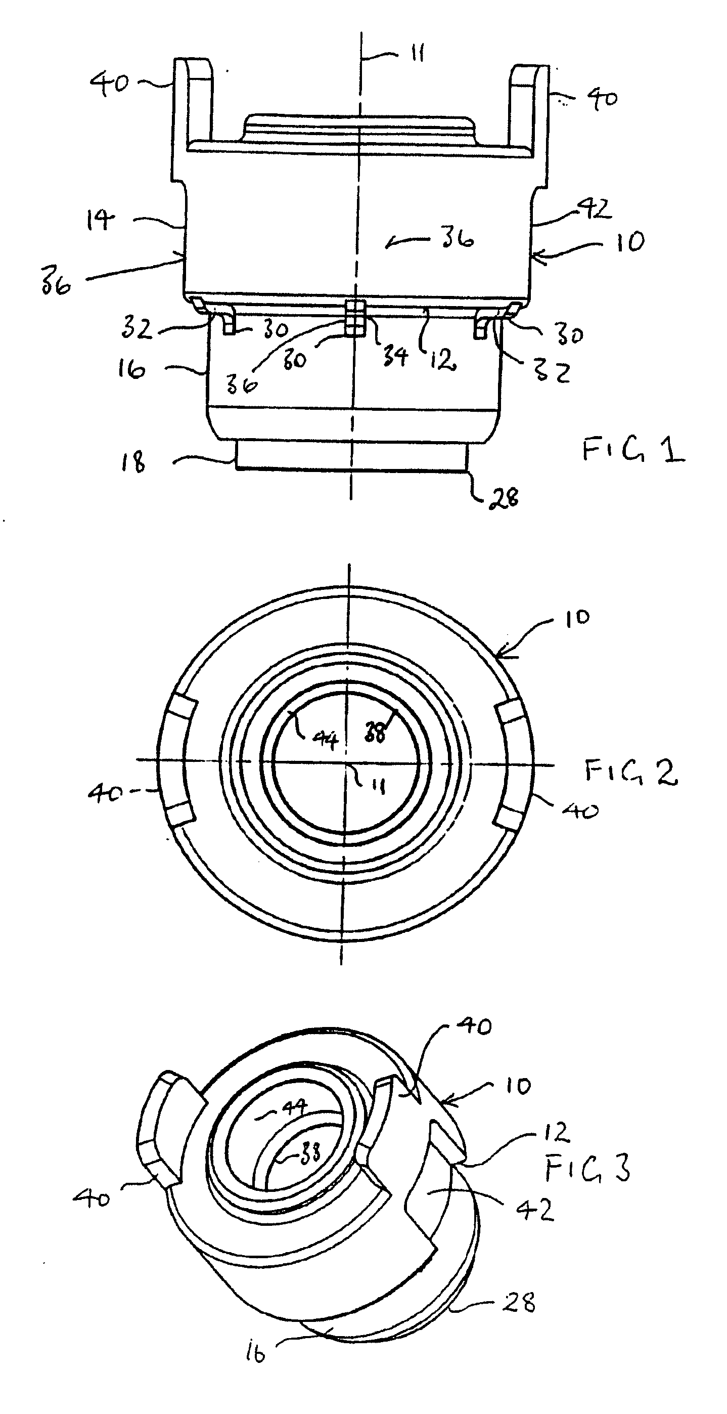
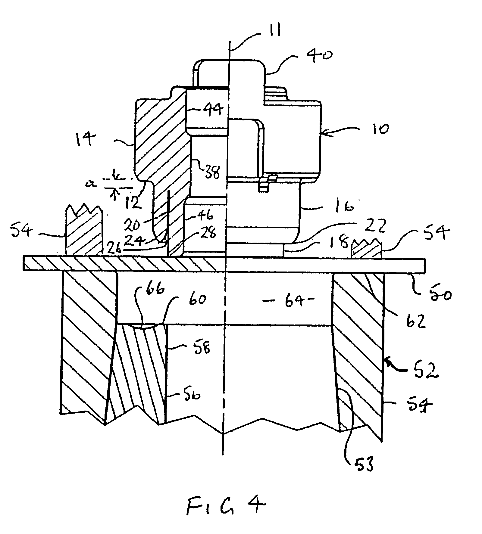
[0051]Referring to FIGS. 1 to 4 the fastener element 10 shown there is provided with a head part 14 having a ring-like contact surface 12 and a tubular rivet section 16 provided at the side of the contact surface 12 of the head part 14 and extending away from the head part 14. The fastener element has a central longitudinal axis 11. A tubular guide section 18 is arranged concentric to the tubular rivet section 16 and radially within the latter, with a ring gap 20 being provided between the guide section 18 and the rivet section 16, the ring gap only being visible in FIG. 4.

[0052]As can likewise be seen from FIG. 4 the free end 22 of the wall of the ring-like rivet section 16 is rounded when viewed in the axial section plane of FIG. 4 both at the radially outer side 24 and also at the radially inner side 26 and has here a rounded shape resembling an arrow-tip. The tip of shape resembling an arrow-tip could however likewise be rounded, which would result in a semicircular shape, which...


PUM

PropertyMeasurementUnit
Lengthaaaaaaaaaa
Lengthaaaaaaaaaa
Electrical conductivityaaaaaaaaaa

Abstract

The invention relates to a method for creating an electrically conductive connection between an electric terminal device having a cavity, such as a cable shoe, and a sheet metal part. According to said method, a hollow fixing element is riveted to the sheet metal part to prevent torsion, thus producing an electrically conductive connection between the fixing element and the sheet metal part and the assembled component is then provided with an electrically non-conductive or poorly conductive protective coating, such as for example a lacquer coating or powder coating. Said method is characterized in that a receptacle for the electric terminal device is configured in the vicinity of the front face of the fixing element, to which the electric terminal device is attached, said receptacle preventing the torsion of the terminal device in relation to the fixing element and the sheet metal part and that a thread forming or cutting screw is screwed through the cavity of the electric terminal device into the hollow fixing element, said screwing action forming or cutting a thread. The invention also relates to a corresponding fixing element and an assembled component that is produced in this manner.

Description

CROSS-REFERENCE TO RELATED APPLICATION[0001]This application is a divisional of U.S. patent application Ser. No. 10 / 528,279 filed Mar. 17, 2005, which claims priority from a continuation-in-part application U.S. patent application Ser. No. 10 / 472,648 filed Mar. 21, 2002, which claims priority of PCT / EP03 / 007436 filed Jul. 9, 2003 and of Germany patent application No. 102 43 759.9 filed Sep. 20, 2002, and the complete contents of that application are incorporated herein by reference.[0002]The present invention relates to a method for producing an electrically conductive connection between an electrical terminal device having a cutout, such as a cable shoe, and a sheet metal part, in which a hollow fastener element is rotationally fixedly riveted to the sheet metal part and an electrically conductive connection is hereby produced between the fastener element and the sheet metal part and the so manufactured component assembly is subsequently provided with an electrically non-conductive...

Claims


Application Information

Patent Timeline
IPC IPC(8): F16B37/04F16B37/06H01R4/30H01R4/64H01R4/66
CPCF16B37/062F16B37/065F16B37/068Y10T29/49208H01R4/64H01R4/66Y10T29/49943H01R4/305
Inventor BABEJ, JIRIHUMPERT, RICHARDVIETH, MICHAEL
Owner PROFIL VERBINDUNGSTECHN
Why Eureka
Eureka Blog
Learn More