Pilot nozzle heat shield having connected tangs

a pilot nozzle and heat shield technology, applied in the field of turbine engines, can solve the problems of warping or clogging of unprotected pilot nozzles, dramatic decrease in the efficiency with which the pilot nozzle operates, and fuel passing through is subject to coking, so as to reduce the incidence of heat shield failure and reduce maintenance down time

Active Publication Date: 2008-02-05
SIEMENS ENERGY INC
View PDF13 Cites 19 Cited by
  • Summary
  • Abstract
  • Description
  • Claims
  • Application Information

AI Technical Summary

Benefits of technology

[0008]Accordingly, there is a need to address the problems encountered in prior art pilot nozzles. Therefore, it is an object of the present invention to provide an improved pilot nozzle heat shield. More, specifically, there is a need for a pilot nozzle heat shield having connected tangs, resulting in a reduction of the incidence of heat shield failure and maintenance down time.
[0010]In a further embodiment, the pilot nozzle heat shield has slots between any two connected tangs. The slots extend distally to a stress relief hole that is preferably located proximal to the aperture. The stress relief hole prevents the tangs from cracking or breaking apart due to the bending or torquing of the tangs caused by the volatile environment of the combustion chamber.

Problems solved by technology

Because of the volatile environment of the combustion chamber, i.e. extreme heat, pressure and vibration, unprotected pilot nozzles are subject to warping or clogging and the fuel passing therethrough is subject to coking.
Such warping or clogging of the pilot nozzle results in a dramatic decrease in the efficiency with which the pilot nozzle operates as well as the combustion facilitated thereby.
Inefficient combustion results in a significant increase in operating costs in a number of ways, including increased fuel consumption, a loss in the amount of power the turbine produces and increased nitrogen oxide emissions.
Facilities releasing greater amounts of NOx emissions than allowed under permit can be subjected to fines or additional permitting requirements, thereby increasing costs.
These prior art heat shields generally have suffered a number of problems including fuel flow obstruction and air flow obstruction.
The separated tang heat shield has been a significant improvement over prior cooling systems, however, this design too suffers a number of problems.
One major problem of the separated tang heat shield is due to a bending or warping of the individual tangs.
The change in the shape of the heat shield results in a disruption of the fluid air flow through the heat shield as well as a disruption in the fluid flow of the pilot fuel from the pilot nozzle.
Once distorted, the resulting effect is a decrease in reliability and efficiency, resulting in engine down time for heat shield replacement.
Such a process can increase the amount of maintenance downtime as well as the monetary costs associated with maintaining the turbine engine.

Method used


Image

  • Pilot nozzle heat shield having connected tangs
  • Pilot nozzle heat shield having connected tangs
  • Pilot nozzle heat shield having connected tangs

Examples


Embodiment Construction

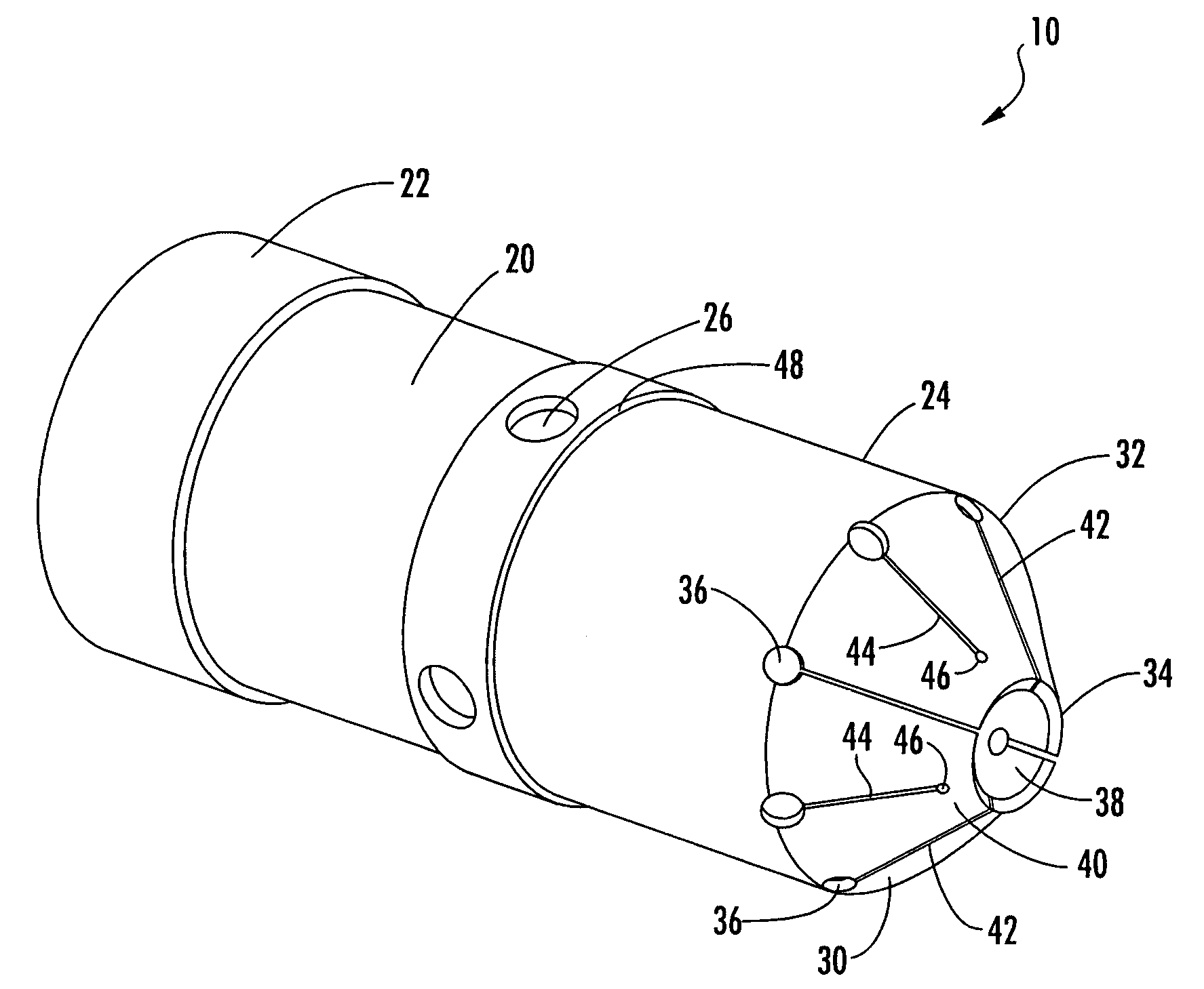
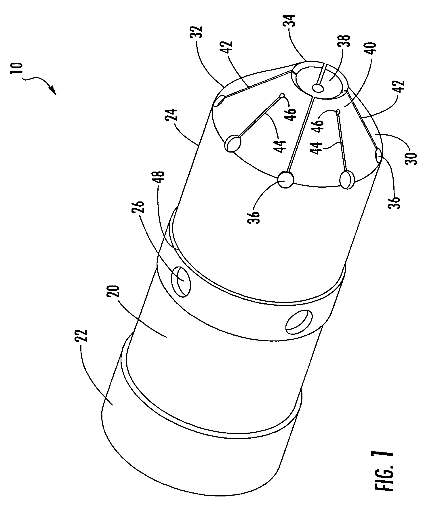
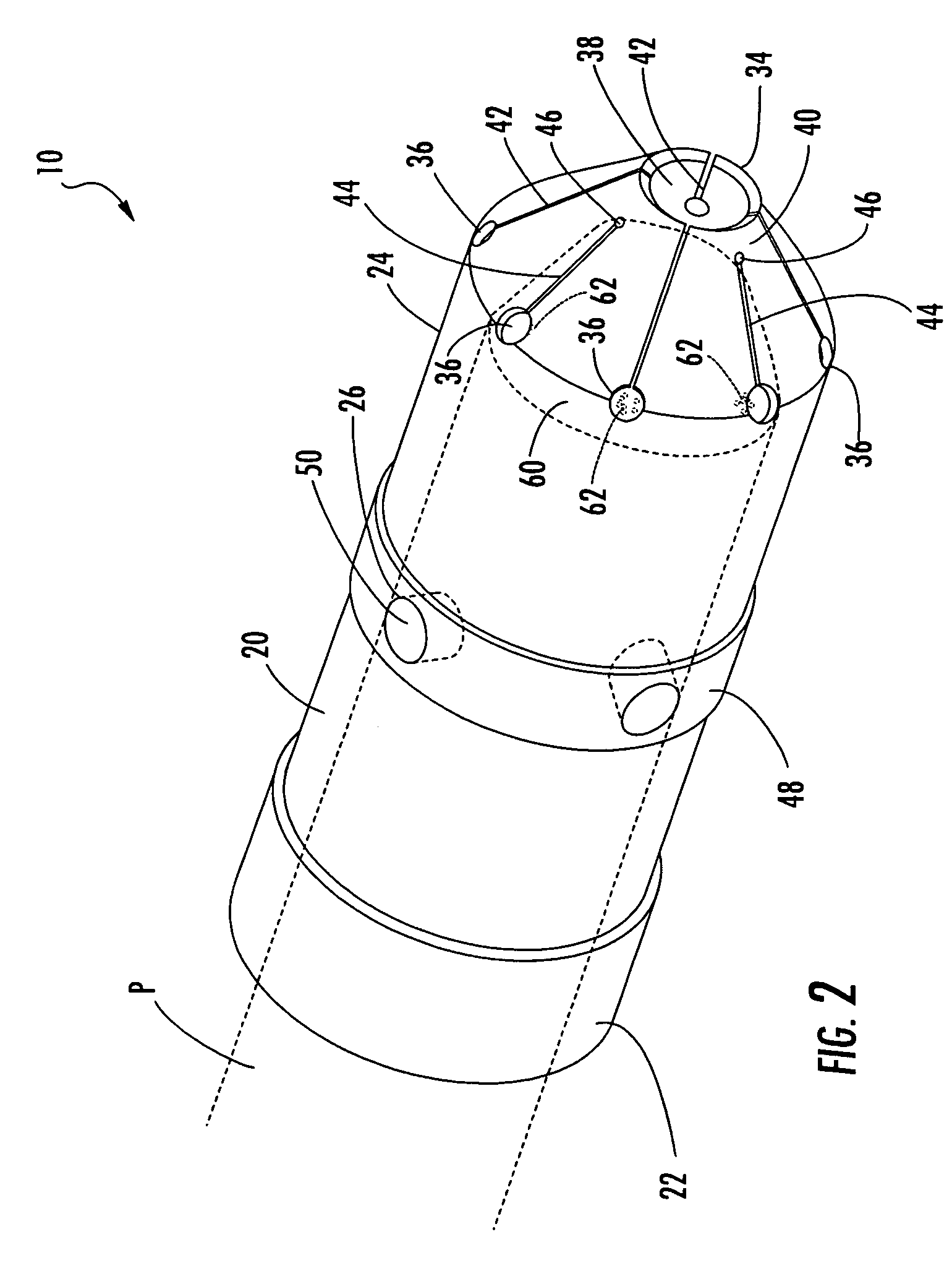
[0021]Referring now to FIGS. 1-6, an exemplary pilot nozzle heat shield according to aspects of the present invention is illustrated and generally referred to by reference numeral 10.

[0022]The heat shield 10 has a body 20. The body 20 is generally cylindrical in shape and comprises a first end 22, a second end 24 and a series of retention pin cavities 26 therebetween. The heat shield 10 can be milled out of a solid piece of heat resistant alloy or cast from the same or similar material. The body 20 is of sufficient size to internally receive the pilot nozzle P (See FIG. 2) and allow sufficient airflow between the pilot nozzle P and the inside of the body 20. The first end 22 of the body 20 can have an internal taper 28 to provide improved air flow through the heat shield 10. The heat shield 10 is the main source of heat protection for the pilot nozzle P. The air flowing through the heat shield can operate to decrease the temperature of the heat shield 10 and can act as an additional...


PUM


Abstract

A pilot nozzle heat shield includes a generally cylindrical body having a first end for receiving a pilot nozzle. The body includes a plurality of radial retention pin cavities for receiving retention pins. A frustoconical flow tip is located at a second end of the body that includes a proximal periphery and a distal periphery. A plurality of flow jets are circumferentially spaced about the proximal periphery of the frustoconical flow tip which further includes a plurality of slots extending distally from the plurality of flow jets. The plurality of slots define a plurality of tangs and the plurality of tangs define an aperture at the distal periphery of the flow tip. At least two of the tangs are connected about the distal periphery of the flow tip and the pilot nozzle heat shield generally includes at least two sets of connected tangs.

Description

FIELD OF THE INVENTION[0001]The invention relates in general to turbine engines and, more particularly, to a heat shield for a pilot nozzle.BACKGROUND OF THE INVENTION[0002]Turbine engines can be utilized for a number of purposes including propulsion and electricity generation. Because of the need to keep the turbine operating consistently with shortened periods of maintenance downtime, the state of the turbine engine art is constantly improving. To maintain the desired operating conditions in a turbine engine, one method of improving performance characteristics is by ensuring that the engine has sufficient combustion for operation.[0003]In general, combustion flame in the combustion chamber of a turbine engine is facilitated by a series of fueled pilot nozzles which provide flame under pressure to the combustion chamber. Because of the volatile environment of the combustion chamber, i.e. extreme heat, pressure and vibration, unprotected pilot nozzles are subject to warping or clogg...

Claims


Application Information

Patent Timeline
Patent Type & Authority Patents(United States)
IPC IPC(8): F02C7/22
CPCF23D14/48F23R3/283F23R3/343F23D2214/00
Inventor PARKER, DAVIDOHRI, RAJEEVBOONSUAN, PLUM
Owner SIEMENS ENERGY INC
Why Eureka
Try Eureka