High flow/dual inducer/high efficiency impeller for liquid applications including molten metal

a technology of impeller and high flow, which is applied in the direction of machines/engines, stators, liquid fuel engines, etc., can solve the problems of reducing the pump flow capacity and the available inlet velocity, and achieve the effect of efficient discharge of metal and high recirculation and gas injection efficiency

Active Publication Date: 2008-02-05
MORANDO JORGE A
View PDF7 Cites 114 Cited by
  • Summary
  • Abstract
  • Description
  • Claims
  • Application Information

AI Technical Summary

Benefits of technology

[0004]A problem with a conventional pump having an excessive height is a tendency to suck dross into the pump, which is undesirable. To compensate, the pump inlet speed is reduced. Reducing the available inlet velocity reduces the pump flow capacity.
[0005]In my design, the impeller that moves the metal has a top plate with a radial inlet opening that serves as an inducer. The molten metal passes through the impeller inducer top plate to a horizontal impeller inducer outlet and then into the collector volute in the pump base. The impeller pump achieves three times the molten metal flow rate, without increasing the motor size three times. The reason is that a dual inducer generates higher outlet impeller tip velocity, thus generating higher pressures and flows, consequentially increasing both the mechanical and volumetric efficiencies of the pump.
[0006]The top plate of the pump has several inlet inducer openings, typically five to seven, which scoop the molten metal into the rotating pump. Each impeller top plate inlet passage has a chamfered entrance or inducer facing the approaching metal. The chamfered leading edge sucks the molten metal axially down, and the chamfered trailing edge further accelerates the metal downwardly increasing the metal flow velocity.
[0008]The high recirculation and gas injection efficiency of the metal flow is achieved by making the pump exit velocity as high as necessary to efficiently discharge the metal so as to penetrate the metal pool outside the pump.
[0009]The impeller contains an exit inducer as well. Using two inducers is also novel. The impeller exit inducer controls the metal flow exit angle, from the impeller, and the metal flow speed, allowing the designer to vary the pump flow versus pressure characteristics, and to select an optimum volute configuration for the particular application under consideration.

Problems solved by technology

A problem with a conventional pump having an excessive height is a tendency to suck dross into the pump, which is undesirable.
Reducing the available inlet velocity reduces the pump flow capacity.

Method used


Image

  • High flow/dual inducer/high efficiency impeller for liquid applications including molten metal
  • High flow/dual inducer/high efficiency impeller for liquid applications including molten metal
  • High flow/dual inducer/high efficiency impeller for liquid applications including molten metal

Examples


Embodiment Construction

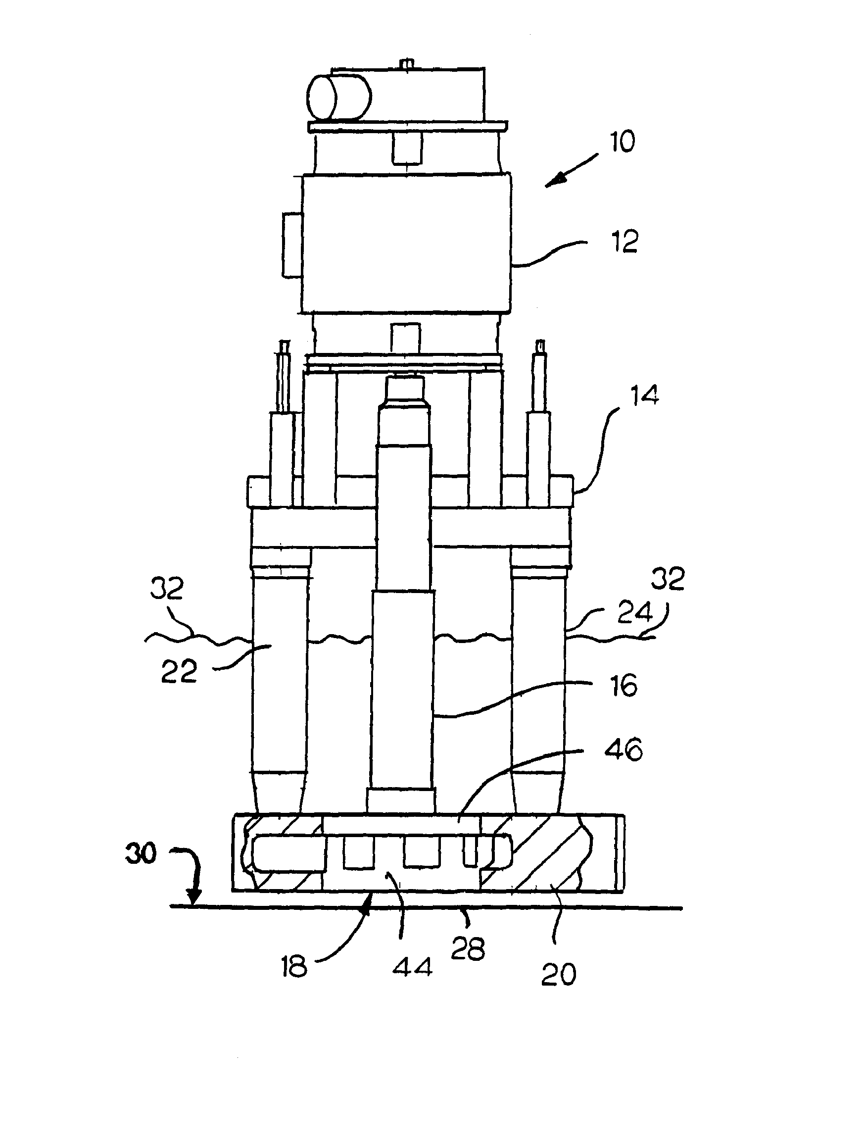
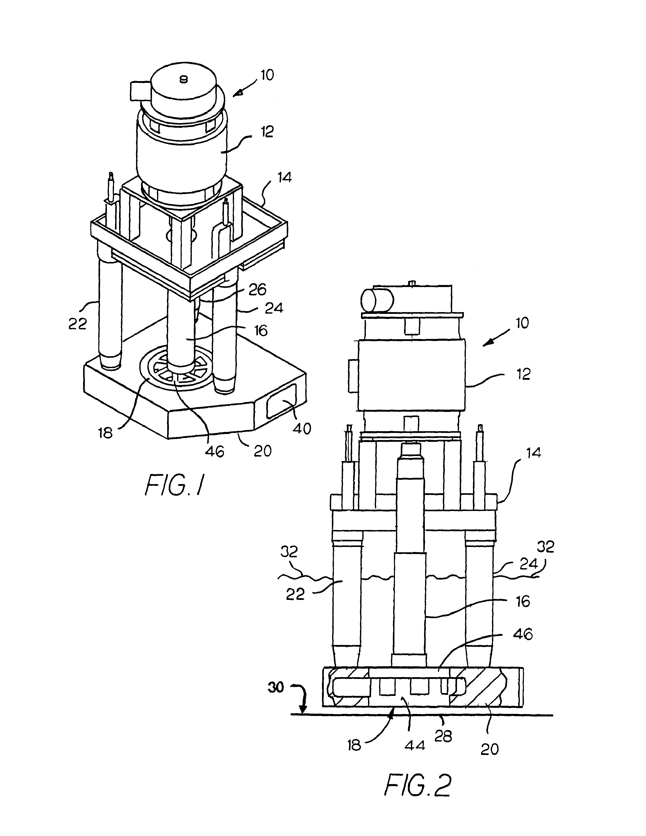
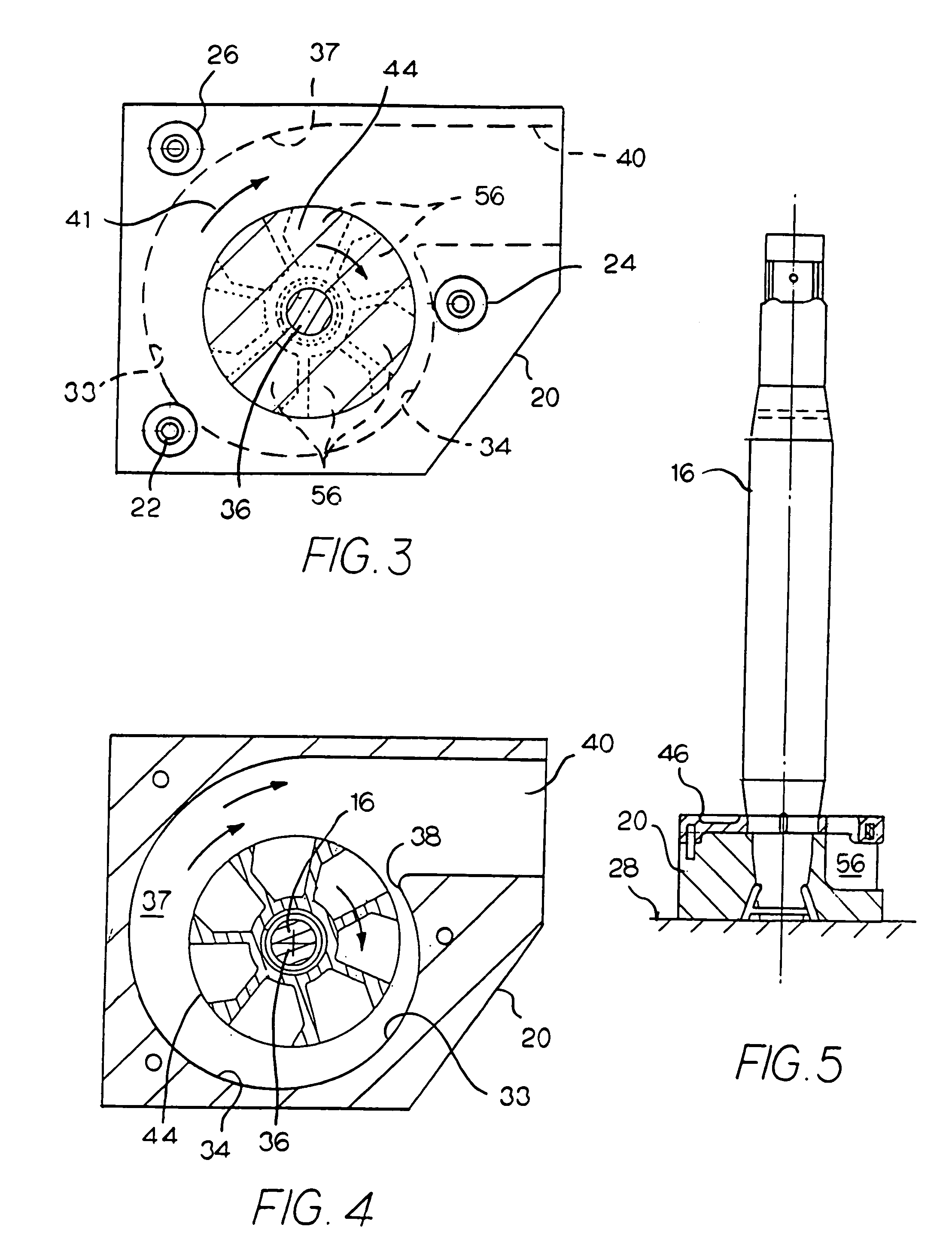
[0033]A preferred centrifugal pump 10, illustrated in FIGS. 1 and 2, comprises a motor 12, supporting structure 14, a vertical shaft 16 and a centrifugal impeller pump 18 mounted in a base 20 formed of either graphite or ceramic.

[0034]Supporting structure 14 and motor 12 are mounted on the upper ends of three vertical posts 22, 24 and 26. The three posts have their lower ends attached to base 20. The impeller is inserted in the base and jointly becomes the pump. Shaft 16 connects the motor to impeller 18. The motor and supporting structure are chosen according to the pumping requirements. The supporting structure also accommodates the furnace (well) which holds the molten metal.

[0035]Pump base 20 is mounted 1.0″ to 2.0″ above furnace bottom 28 of a well 30 which contains a quantity of molten metal having a top surface 32. The location of the base is near the bottom of the well to provide a pressure head above the pump intake, permitting the use of a more compact pumping unit and a m...


PUM


Abstract

A centrifugal pump has a pump base with inlet inducer openings that receive molten metal into an impeller chamber. An impeller structure in the impeller chamber passes the metal in a radial direction through an outlet inducer opening into a volute passage for discharge into the pool of metal in which the pump is located.

Description

CROSS-REFERENCE TO RELATED APPLICATION[0001]This application claims domestic priority of Provisional Patent Application filed Apr. 28, 2005, Ser. No. 60,675,828 for HIGH FLOW / DUAL INDUCER / HIGH EFFICIENCY IMPELLER FOR LIQUID APPLICATIONS INCLUDING MOLTEN METAL.BACKGROUND AND SUMMARY OF THE INVENTION[0002]A typical molten metal facility includes a furnace with a pump for moving molten metal. This invention provides a centrifugal impeller pump that will move more molten metal with a minimum of submergence while retaining a very high overall efficiency. This goal is achieved by accelerating flow into the impeller pump by utilizing the full available pressure head of metal above the pump.[0003]An optimum head is acquired by making my pump very shallow and locating it on the bottom of the well.[0004]A problem with a conventional pump having an excessive height is a tendency to suck dross into the pump, which is undesirable. To compensate, the pump inlet speed is reduced. Reducing the avai...

Claims


Application Information

Patent Timeline
Patent Type & Authority Patents(United States)
IPC IPC(8): F04D1/12
CPCF04D7/065F04D29/2255F04D29/2277Y10S417/90
Inventor MORANDO, JORGE A.
Owner MORANDO JORGE A
Why Eureka
Try Eureka