Shield member

a shield member and shielding technology, applied in the direction of coupling device connection, instruments, standard structures, etc., can solve the problems of common differences in coupling between the two, and achieve the effect of increasing reducing the length of the shield member and the cost of material

Inactive Publication Date: 2008-02-05
INVENTEC CORP
View PDF9 Cites 8 Cited by
  • Summary
  • Abstract
  • Description
  • Claims
  • Application Information

AI Technical Summary

Benefits of technology

[0014]In contrast to prior techniques that necessitates increasing the length of the shield member so that more slide blocks can be disposed thereon, the shield member of the invention employs an elastic portion thereof that elastically contacts the wall of the slot so as to be smoothly and tightly inserted in the slot, thereby reducing the length thereof and the material cost as a result.
[0015]The elastic portion is tightly inserted into the slot along with the insertion of the body in the slot of the electronic device, which eliminates a problem of getting stuck caused by the swing insertion due to the uneven pressure exerted thereto.
[0016]The slot of the electronic device is provided with a first connecting tab and a second connecting tab is disposed on a side surface of the body that corresponds to an outer edge of the first connecting tab, thereby positioning to meet the insertion depth of the shield member in the slot, which ensures that the shield member does not get stuck in the slot by using its elastic portion to enable the second connecting tab thereof to connect and abut against the first connecting tab, thereby overcoming the drawback of disengagement from one another as occurred in the prior art.
[0017]Further, the shield member of the invention can include a plurality of third connecting tabs to connect and abut against an existing structure provided in the slot when the body is inserted into the slot, thereby enforcing the insertion and spreading the pressure exerted to the first connecting tab. The present invention offers advantages over the prior art techniques as it has been proved to easily pass the drop tests and have industrial applicability.

Problems solved by technology

However, in the foregoing structure, there exists a drawback of the insufficient coupling between the shield member 12 and the slot 10 by the slide block 120 in that the slide block does not have the flexibility required to be tightly abut against the wall of the slot 10, resulting in a common difference of coupling between the two.

Method used


Image

  • Shield member
  • Shield member
  • Shield member

Examples


Embodiment Construction

[0022]The present invention is described in the following so that one skilled in the pertinent art can easily understand other advantages and effects of the present invention. The present invention may also be implemented and applied according to other embodiments, and the details may be modified based on different views and applications without departing from the spirit of the invention.

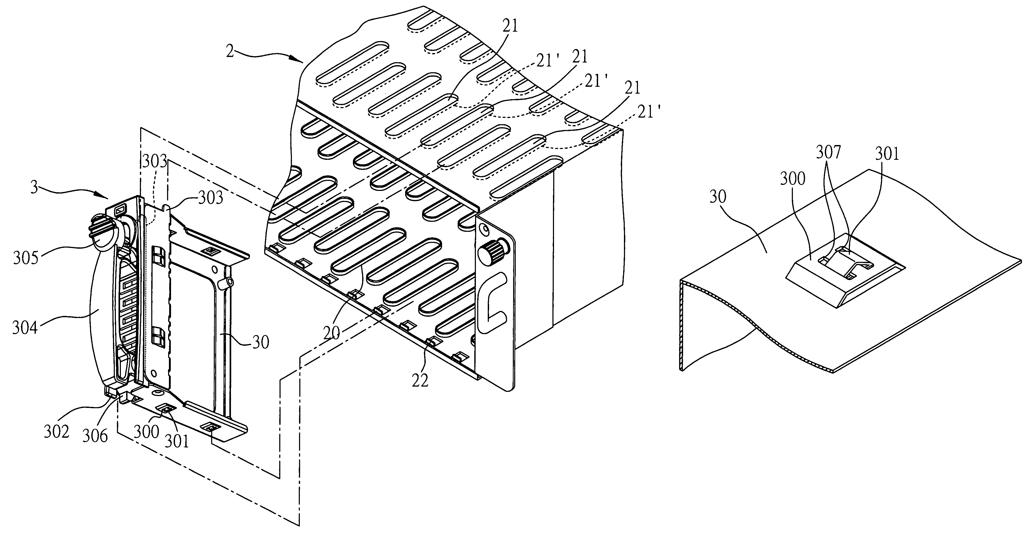
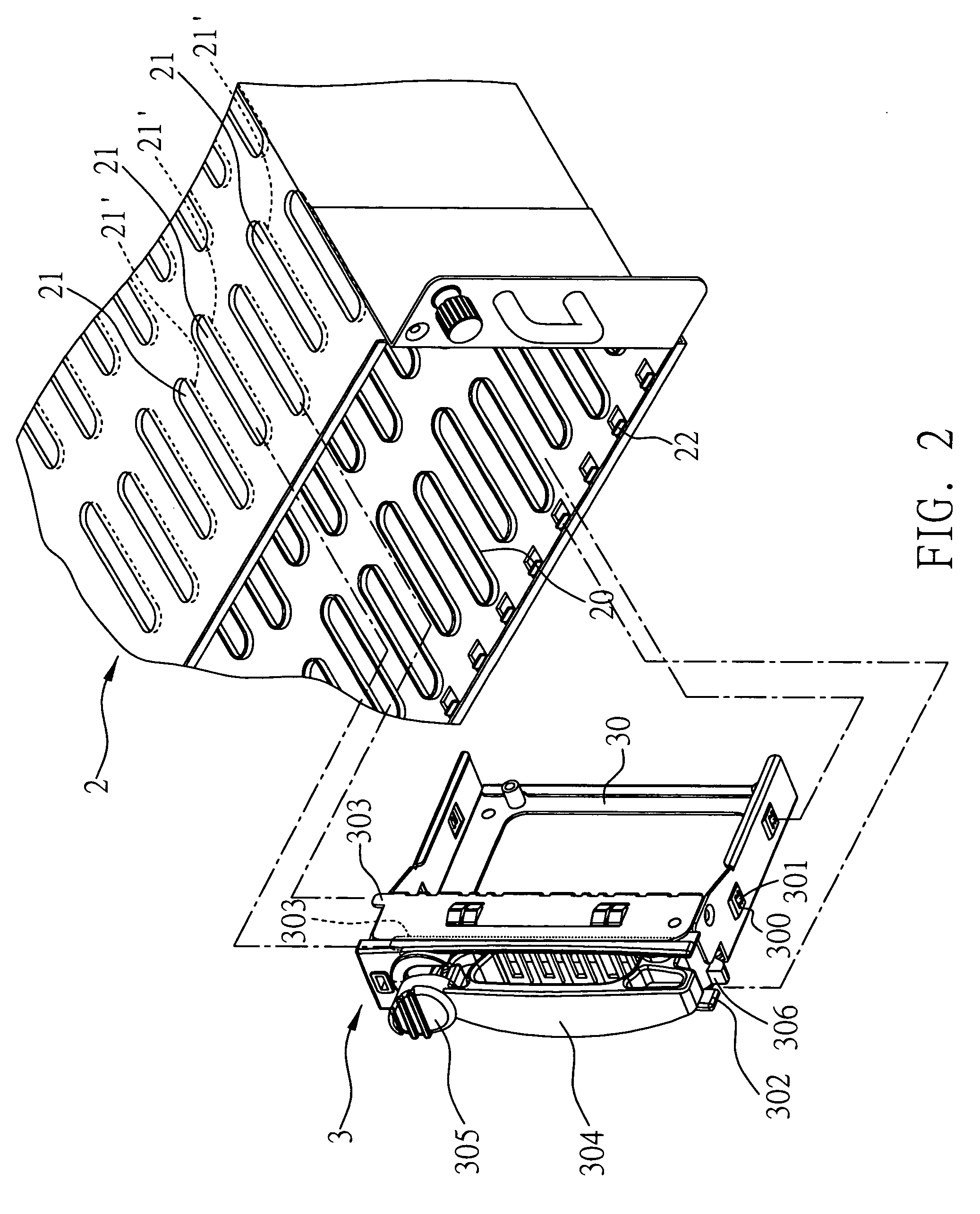
[0023]Referring to FIG. 2, a slot 20 of an electronic device 2 covered by a shield member 3 of the present invention is illustrated, wherein the electronic device 2 may be a server and the slot 20 is an inserting groove for carriers carrying hard disk (not shown) to be inserted therein; the electronic device 2 may also be a blade server and the slot 20 is an inserting groove for the blade bracket to be inserted therein.

[0024]The shield member 3 of the present invention comprises a body 30 for inserting and pluggable into the slot 10; a slide block 300 disposed on the surface of the body 30 and corre...


PUM


Abstract

The present invention provides a shield member for covering the slot of an electronic device, including at least a body for inserting and pluggable into the slot; a slide block disposed on the surface of the body and corresponding to the slot; and an elastic portion disposed on the surface of the slide block and elastically contacting the wall of the slot for the body to be tightly inserted into the slot. The invention employs the elastic portion to allow a body having a minimum length required to be inserted tightly into the slot, thereby reducing the material cost.

Description

BACKGROUND OF THE INVENTION[0001]1. Field of the Invention[0002]The present invention relates to shielding members, and more particularly, to a shield member for covering a slot of an electronic device.[0003]2. Description of Related Art[0004]The primary function of an industrial server is to store massive data therein, and the hardware thereof is generally carried by carriers to be plugged into a plurality of slots of the server by way of hot swap.[0005]Referring to FIG. 1, a server 1 having a plurality of slots 10 for receiving hard disk carriers 11 therein is illustrated, in which unused slots 10 are covered by a shield member 12 for shielding the slots from dust and electromagnetic interference. Users may choose among different manufacturers the appropriate servers having a sufficient number of slots that suit to their needs; on the other hand, spare slots are often reserved for emergency use and convenient replacement in the case of an electric breakdown of the slots in use.[00...

Claims


Application Information

Patent Timeline
Patent Type & Authority Patents(United States)
IPC IPC(8): H01R13/64
CPCG06F1/187G11B33/12H05K9/0062
Inventor HSU, YUNG-CHIN
Owner INVENTEC CORP
Why Eureka
Try Eureka