Intravascular stent

a stent and stent technology, applied in the field of intravascular stents, can solve the problems of reducing the most serious drawback of balloon-based angioplasty, and the limited effectiveness of ancillary technologies such as laser based treatment, etc., to achieve the effect of reducing the “hang up” of the vessel and increasing the radial and axiolateral strength of the expanded sten

Inactive Publication Date: 2008-02-05
BOSTON SCI SCIMED INC
View PDF316 Cites 131 Cited by
  • Summary
  • Abstract
  • Description
  • Claims
  • Application Information

AI Technical Summary

Benefits of technology

[0023]Another object of the invention is to provide a chain mesh stent that reduces vessel “hang up” in a tortuous vessel or a vessel with curvatu

Problems solved by technology

Other ancillary technologies such as laser based treatment, or directional or rotational arthrectomy, have proven to be either of limited effectiveness or dependent on balloon angioplasty for completion of the intended procedure.
Restenosis following balloon-based angioplasty is the most serious drawback and is especially prevalent in the coronary artery system.
Many regimens have been designed to combat restenosis, with limited success, including laser based treatment and directional or rotational arthrectomy.
Intravascular stenting, however, noticeably reduces the restenosis rate following angioplasty procedures.
Early in its development, the practice of stenting, especially in coronary arteries, had serious anticoagulation problems.
The unexpanded tubular members of the Palmaz Patent are overly rigid so that practical application is limited to short lengths.
Even with implementation of the multilink design with flexible connector members connecting a series of tubular members, longer stents can not navigate tortuous blood vessels.
Furthermore, the rigidity of the unexpanded stent increases the risk of damaging vessels during insertion.
Foreshortening of the stent during inserti

Method used


Image

  • Intravascular stent
  • Intravascular stent
  • Intravascular stent

Examples


first embodiment

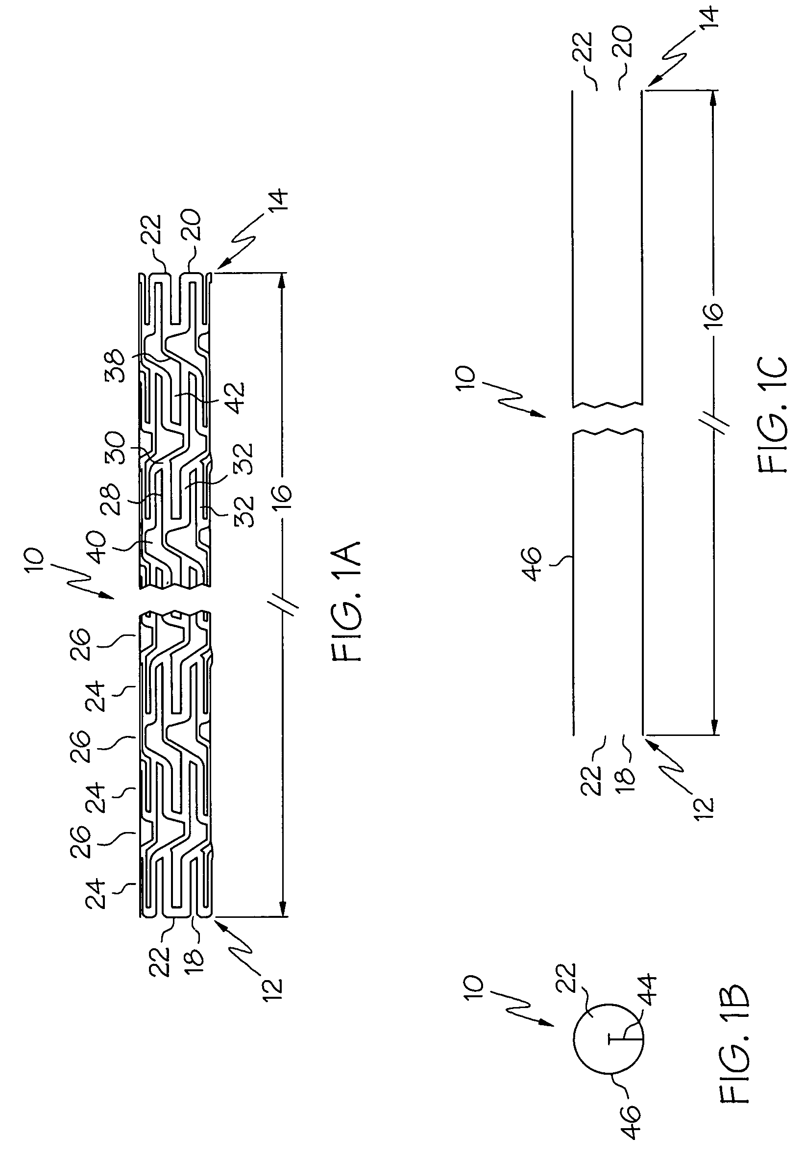
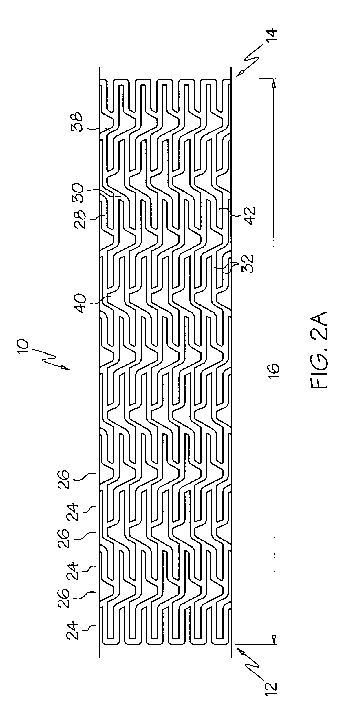
[0066]the present invention is shown in FIGS. 1A, 1B, 1C, 2A and 2F. Referring to FIG. 1A, an elongate hollow tubular stent 10 in an unexpanded state is shown. A proximal end 12 and a distal end 14 define a longitudinal length 16 of stent 10. The longitudinal length 16 of the stent 10 can be as long as 100 mm or longer. A proximal opening 18 and a distal opening 20 connect to an inner lumen 22 of stent 10. Stent 10 can be a single piece, without any seams or welding joints or may include multiple pieces.

[0067]Stent 10 is constructed of two to fifty or more expansion columns or rings 24 connected together by interspersed connecting strut columns 26. The first column on the proximal end 12 and the last column on the distal end 14 of stent 10 are expansion columns 24.

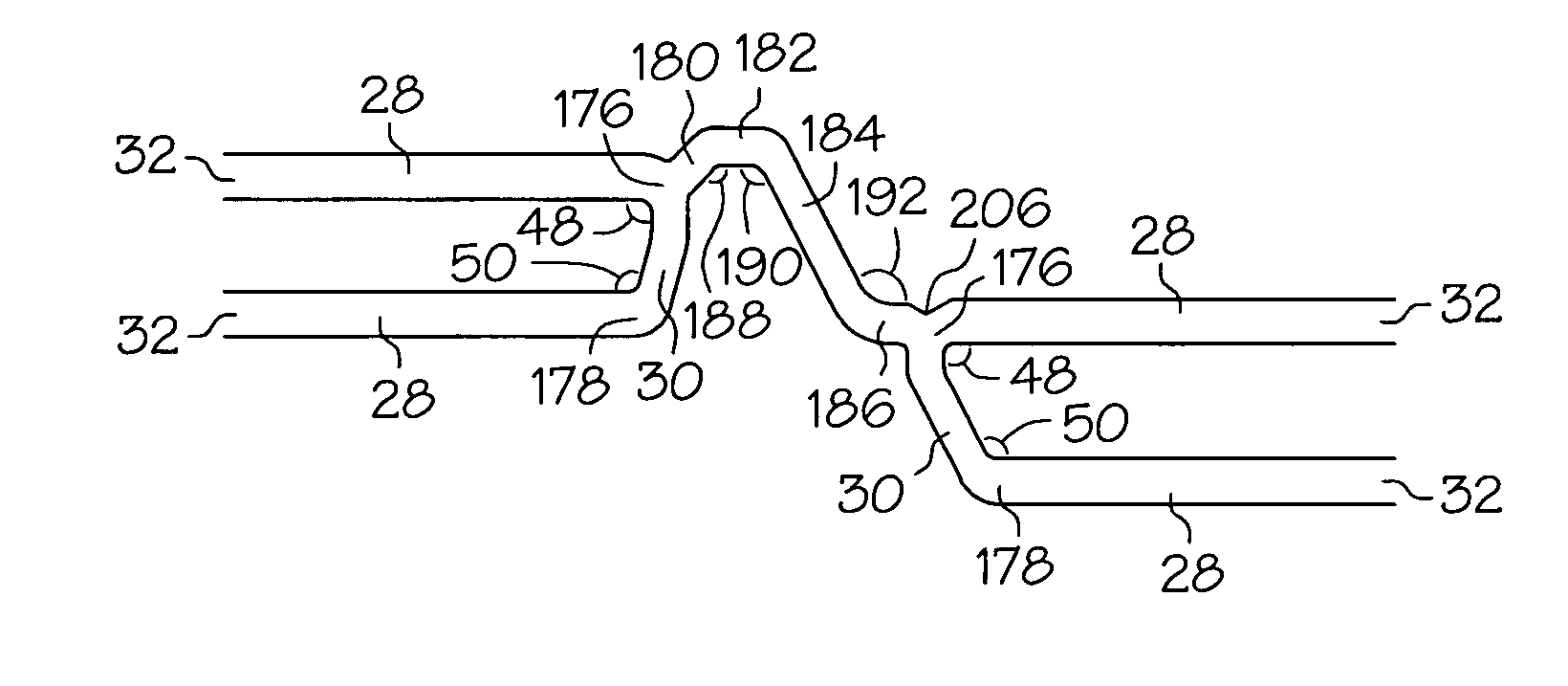
[0068]Expansion columns 24 are formed from a series of expansion struts 28, and joining struts 30. Expansion struts 28 are thin elongate members arranged so that they extend at least in part in the direction of the longitu...

second embodiment

[0092]FIG. 5 shows the present invention in which the stent 10 in its expanded form has a gradual taper from proximal end 12 to distal end 14. The shaded segments 72, 74, 76, 78, 80, 82 and 84 of expansion struts 28 represent regions of expansion struts 28 to be removed. Removal of the shaded segments 72, 74, 76, 78, 80, 82 and 84 provides stent 10 with a gradual taper when expanded with distal end 14 having a smaller expanded diameter than proximal end 12. The degree of shortening of the expanded diameter of the stent 10 at a given expansion column 24 will be proportional to the length of the removed segment 72, 74, 76, 78, 80, 82, or 84 at that expansion column 24. In the expanded stent 10 the shortened expansion struts 28 will have a shortened component along the circumference of the stent resulting in a shortened circumference and diameter. The tapered diameter portion can be positioned anywhere along the length of stent 10, and the tapering can be made more or less gradual by r...

third embodiment

[0097]the present invention shown in FIGS. 6A and 6B has multiple reenforcement expansion columns 86 placed along the length of the stent 10. The Reenforcement columns 86 are placed along the stent length to provide additional localized radial strength and rigidity to stent 10. Additional strength and rigidity are especially important at the ends of the stent to prevent deformation of the stent both during delivery and after placement. During delivery the stent ends can catch on the vessel wall possibly deforming the unexpanded stent and altering its expansion characteristics. After the stent has been placed it is important that the stent ends are rigid so that they set firmly against the vessel wall; otherwise, during a subsequent catheter procedure, the catheter or guidewire can catch on the stent ends pulling the stent away from the vessel wall and possibly damaging and / or blocking the vessel.

[0098]The specific variation of the third embodiment of stent 10 depicted in FIGS. 6A an...


PUM


Abstract

A stent in a non-expanded state has a first and second expansion column, each consisting of a plurality of expansion strut pairs. An expansion strut pair includes a first expansion strut, a second expansion strut and a joining strut that couples the first and second expansion struts at one end. Expansion strut pairs include expansion strut pair first and second corners formed where the joining strut couples the first and second expansion struts. A connecting strut column, formed of a plurality of connecting struts couples the first and second expansion columns. Connecting struts include a proximal section, a distal section and an intermediate section. The proximal section is coupled to the corner of an expansion strut pair of the first expansion column, and the distal section is coupled to the joining strut of an expansion strut pair of the second expansion column intermediate the expansion strut pair first corner and the expansion strut pair second corner.

Description

CROSS-REFERENCE TO RELATED APPLICATIONS[0001]This application is a continuation of U.S. patent application Ser. No. 09 / 574,077 filed May 18, 2000 now U.S. Pat. No. 6,770,088, which is a continuation of U.S. patent application Ser. No. 08 / 845,734 filed Apr. 25, 1997 now abandoned which is a continuation-in-part of U.S. patent application Ser. No. 08 / 824,142 filed Mar. 25, 1997 now U.S. Pat. No. 6,241,760, and a continuation-in-part of U.S. patent application Ser. No. 08 / 824,866 filed Mar. 26, 1997 now U.S. Pat. No. 5,954,743 and a continuation-in-part of U.S. patent application Ser. No. 08 / 824,865 filed Mar. 26, 1997 now U.S. Pat. No. 6,152,957 and is a continuation-on-part of U.S. patent application Ser. No. 08 / 845,657 filed Apr. 25, 1997 now U.S. Pat. No. 5,922,021 all of which are incorporated herein by reference. Said application Ser. No. 09 / 574,077 claims the benefit of Provisional Patent Application No. 60 / 017,484 filed Apr. 26, 1996, the disclosure of which is incorporated by ...

Claims


Application Information

Patent Timeline
IPC IPC(8): A61F2/06A61F2/00A61F2/84A61F2/90
CPCA61F2/91A61F2/915A61F2/958A61F2230/0054A61F2002/91533A61F2002/91558A61F2250/0018A61F2002/91525
Inventor JANG, G. DAVID
Owner BOSTON SCI SCIMED INC
Why Eureka
Try Eureka