Knife guard construction for sickle knife

a technology of sickle knife and blade guard, which is applied in the field of crop cutting device, can solve the problems of crop engaging this front edge rather than the side cutting edge of the blade, affecting crop yield, and affecting crop yield

Active Publication Date: 2008-02-12
MACDON INDS
View PDF18 Cites 62 Cited by
  • Summary
  • Abstract
  • Description
  • Claims
  • Application Information

AI Technical Summary

Benefits of technology

[0110]Another feature of the arrangement as described in the embodiments herein is to allow clearance adjustment to ensure tight clearance between all blade cutting surfaces and the respective guard ledger surfaces. At the guards with upper ledger surfaces the upper portion of the guard is mounted to an adjuster bar. This adjuster bar has threaded fasteners that allow the gap between the upper guard ledger surfaces and lower ledger surfaces to controlled precisely.
[0117]In the pointed guard arrangement there is provided a unique bottom guard as previously described at the center with ledger surfaces vertically offset by the thickness of one sickle blade. The conventional tang or shelf that usually covers the top of the section is absent to allow for the top guard to be used. The top guard is formed with two points with but with blunt front edges and ledger surfaces closely matching in width to the ledger surfaces of he bottom guard. The top guard is mounted to an adjuster bar that allows fine vertical adjustment. Another unique feature of the bottom guard is a raised projection at the front of the ledger surface that covers the front edges of the sickle blades and top guard. This prevents crop material from entering from the front and clogging the guard.

Problems solved by technology

As this front edge must have a significant width for strength, there is a risk that crop engages this front edge rather than the side cutting edges of the blade.
One drawback of the stub guard system is that the blunt front edge of the section is fully exposed to the crop entering during the entire sickle stroke cycle.
This presents a barrier to crop entry for any crop directly contacting the front edge of the section.
Several attempts have been made to perfect the area where the inboard ends of the sickles overlap during the inboard stroke near the center of the cutter bar assembly since this has always been a problem area subject to fast wear and / or poor cutting in tough cutting conditions.
However, on the inboard stroke the shearing edges of both sections are spaced one section thickness from the guard ledger surface which is not desirable especially in tough cutting conditions.
However, careful analysis will reveal that the hold downs between the guards hold the sickle bars downwardly, so that the shearing relationship between the upper inverted sections and the upper shearing surface of the special center guards will not be held to tight tolerance especially as the guards and blades start to wear.
The shearing surfaces between the downwardly facing blade and the upwardly facing inverted blade in this center area are two thicknesses of blade apart so that there is no proper shearing action, which is not desirable in tough cutting conditions.
However, some crop gathers between the blades and the guards and has to be cut by the blade as it enters the guard slot.
The shearing surface of the top blades is spaced by the thickness of a blade from the guard upper ledger surface which is not desirable in tough cutting conditions.
This is not desirable in tough cutting conditions.
However the provision of two vertically spaced ledger surfaces requires a large vertical spacing between the two blades and thus the two sickle bars.
This interferes with the ability of the reel, which sweeps the crop past the guards, to be mounted close to and consistently relative to the cutting elements which is desirable for effective cut crop removal.
Secondly there is no effective means of holding the shearing surfaces of the blades at close clearances to the guard ledger surfaces at the overlap.

Method used


Image

  • Knife guard construction for sickle knife
  • Knife guard construction for sickle knife
  • Knife guard construction for sickle knife

Examples


Embodiment Construction

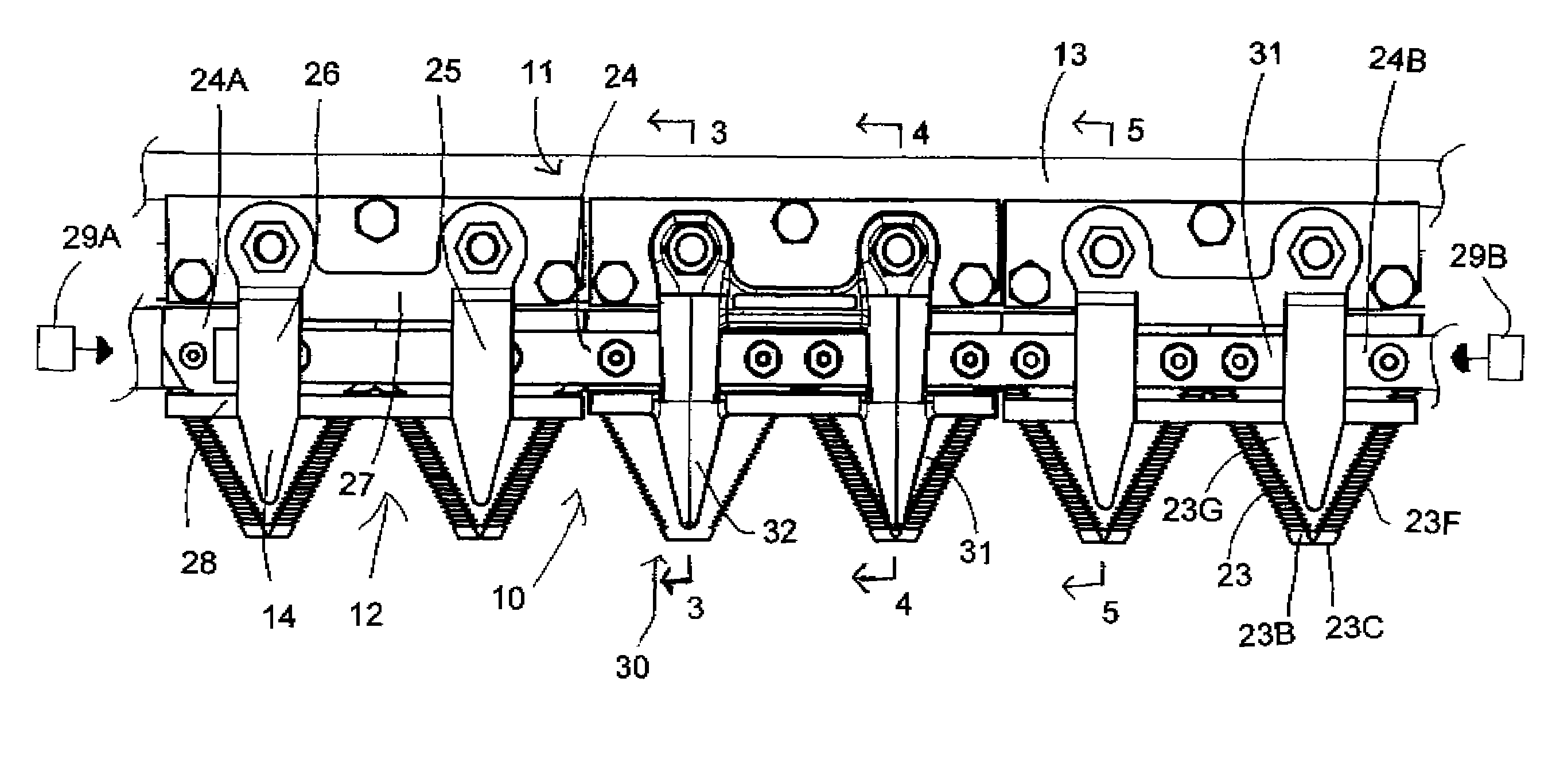
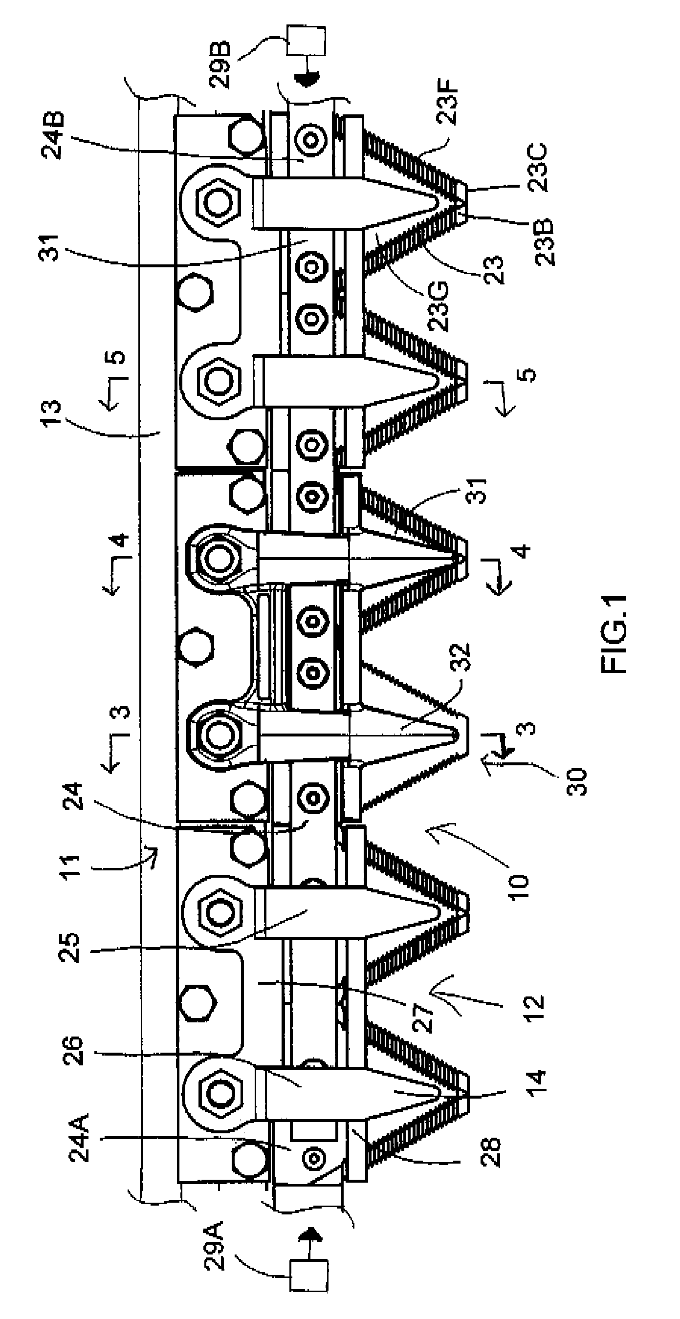
[0130]In FIGS. 1 to 5 is shown a first embodiment of a crop cutting device generally indicated at 10. Only a part of the complete machine is shown since the remainder of the machine may vary widely depending upon requirements and since the construction is of course well known to a person skilled in the art. In this embodiment as shown, there is a frame generally indicated at 11 which of course forms only one part of the total frame structure that is the part of the frame that is relevant to the present invention.

[0131]The cutting device 10 further includes a cutter bar 12 attached to the frame structure 11. Thus the frame structure 11 in the part as shown comprises a guard bar 13 to which is attached a plurality of knife guards 14. The guard bar 13 is attached to a cutter bar 15 along the front edge of a frame structure which supports the guard bar in fixed position across the front edge of the frame for a cutting action of the crop cuffing device on the standing crop.

[0132]The knif...


PUM


Abstract

The center sickle overlap arrangement of a sickle type mower for a cutter bar that include a pair of sickles for reciprocating motion where each sickle is essentially half the length of the cutter bar for reduced forces and vibrations for high speed cutting. In the center, the sickle blades overlap at only guard and the blade of one sickle is inverted and co-operates with a top ledger surface of the associated guard so that both the blades are in proper shearing arrangement with the respective guard ledgers. Further the top ledger surface is adjustable to allow clearance adjustment to ensure tight clearance between all sickle cutting surfaces and guard ledgers. Further the arrangement ensures that all crop is cut between sickle sections and guard ledgers rather than between a pair of sections on the opposing sickles.

Description

[0001]This application claims the benefit under 35 U.S.C. 119 of the filing date of Provisional Application 60 / 818,524 filed Jul. 6, 2006.[0002]This invention relates to a sickle knife type cutter and particularly to a knife guard construction for use for use in cooperating with the knife blades in a cutting action either at a center between two opposed sickle bars or at any point along a sickle bar.BACKGROUND OF THE INVENTION[0003]The present invention relates to a crop cutting device comprising:[0004]a frame structure arranged for forward travel over ground having a standing crop thereon;[0005]a cutter bar secured to the frame structure and extending transversely across a front end of said frame structure;[0006]a plurality of knife guards mounted in spaced relation along said cutter bar and projecting forwardly therefrom in transverse alignment;[0007]each of said guards having an upwardly facing ledger surface with opposed side edges thereof arranged to provide first and second sh...

Claims


Application Information

Patent Timeline
Patent Type & Authority Patents(United States)
IPC IPC(8): A01D34/13A01D34/18
CPCA01D34/135
Inventor SNIDER, GEOFFREY U.JORDAN, DAVID J.TALBOT, FRANCOIS R.
Owner MACDON INDS
Why Eureka
Try Eureka