Integrated adaptive capacity control for a steam turbine powered chiller unit

a technology of adaptive capacity control and chiller unit, which is applied in the direction of machines/engines, refrigeration components, light and heating equipment, etc., can solve the problems of loss of efficiency, inefficiency in the operation of steam turbine driven chiller system, and excessive fieldwork of turbine powered chiller systems, so as to prevent unsafe operation of the system

Inactive Publication Date: 2008-02-12
JOHNSON CONTROLS TYCO IP HLDG LLP
View PDF61 Cites 28 Cited by
  • Summary
  • Abstract
  • Description
  • Claims
  • Application Information

AI Technical Summary

Benefits of technology

[0009]One advantage of the present invention is the integration of the chiller with the steam turbine into a pre-packaged unit.
[0010]Another advantage of the present invention is a central control system for use with both pre-packaged steam turbine driven chiller systems and “as-built” steam turbine driven chiller systems
[0011]Still another advantage of the present invention is a central control system that utilizes the full range of controls for the steam turbine driven chiller system to control the capacity of the chiller and to provide anti-surge and override control functions to prevent unsafe operation of the system.

Problems solved by technology

Typically, these steam turbine powered chiller systems have required an excessive amount of fieldwork to install and connect the chiller system to the steam turbine system.
This independent operation of controls often resulted in inefficiencies in the operation of the steam turbine driven chiller system, as one control operation on one part of the system would remove or limit the efficiency gained from another control operation on another part of the system.
In addition to losses in efficiency, the use of independent controls also limited effective surge prevention in the compressor of the chiller system because the separate systems were not able to measure or monitor the system pressure differential (condenser pressure minus evaporator pressure).

Method used


Image

  • Integrated adaptive capacity control for a steam turbine powered chiller unit
  • Integrated adaptive capacity control for a steam turbine powered chiller unit
  • Integrated adaptive capacity control for a steam turbine powered chiller unit

Examples


Embodiment Construction

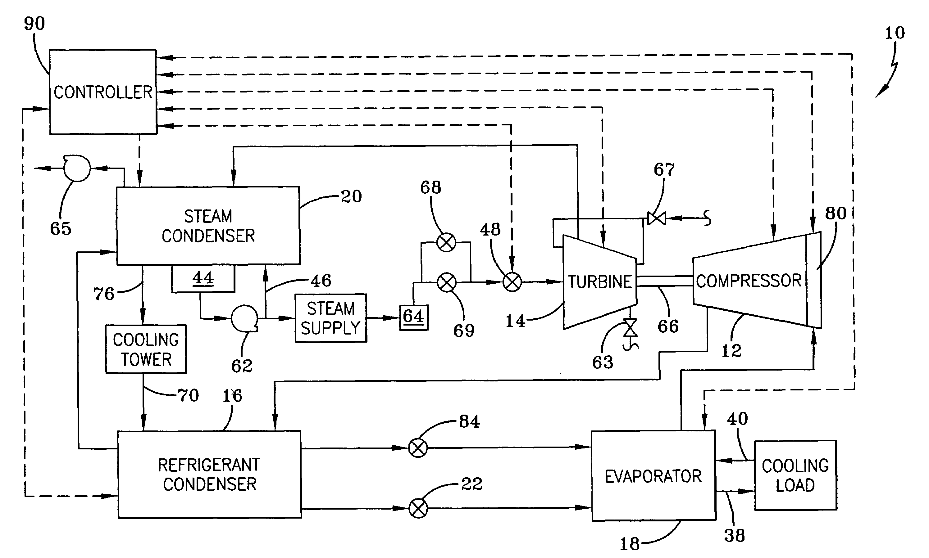
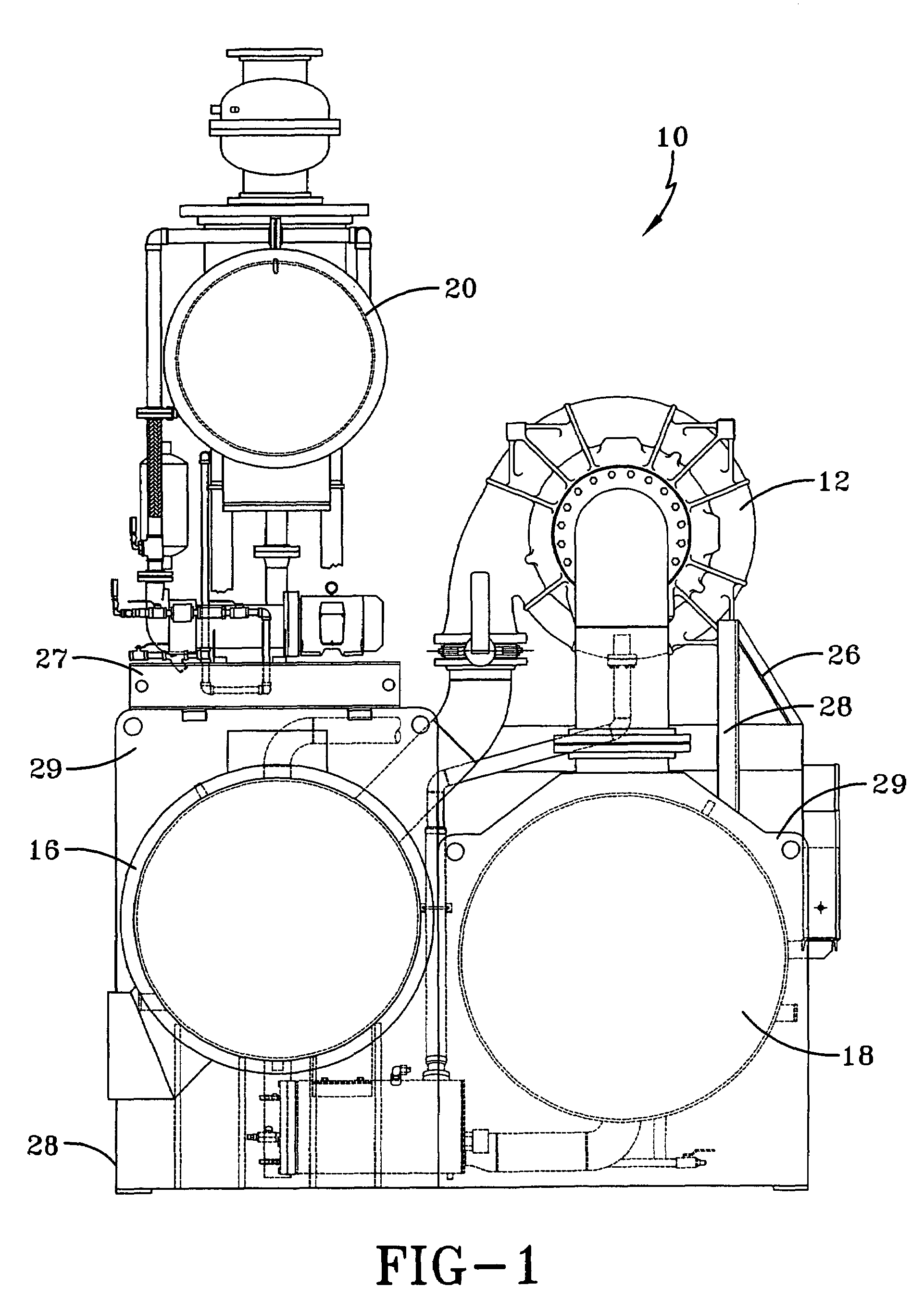
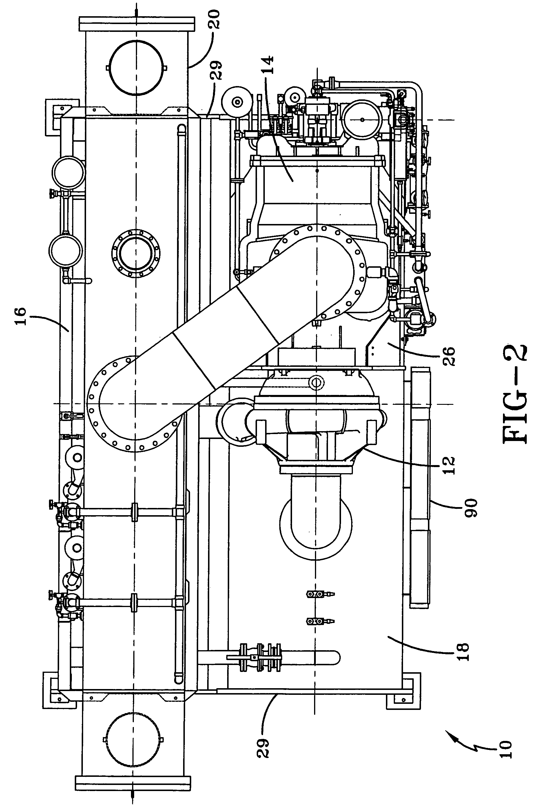
[0023]A general system to which the invention is applied is illustrated, by means of example, in FIGS. 1-3. As shown, the HVAC, refrigeration, or chiller system 10 includes a compressor 12, a steam turbine 14, a refrigerant condenser 16, a water chiller or evaporator 18, a steam condenser 20, an expansion device 22 and a control panel or controller 90. The operation of the control panel 90 will be discussed in greater detail below. The chiller system 10 further includes a compressor lubrication system (not shown) and a turbine lubrication system (not shown). The conventional liquid chiller system 10 includes many other features that are not shown in FIGS. 1-3. These features have been purposely omitted to simplify the drawing for ease of illustration.

[0024]In a preferred embodiment, a “structural frame” permits the stacking or vertical arrangement of the major components of the chiller system 10 to provide a prepackaged unit that occupies less floor space with a smaller footprint th...


PUM


Abstract

A control system for a steam turbine driven chiller unit is provided. The control system automatically utilizes the full range of the governor, compressor pre-rotation vanes, and hot gas bypass valve capabilities to control the capacity of the chiller and provide anti-surge and override control functions to prevent undesirable operational ranges while maintaining maximum efficiency of operation.

Description

CROSS REFERENCE TO RELATED APPLICATIONS[0001]This application claims the benefit of U.S. Provisional Application No. 60 / 539,014, filed Jan. 23, 2004.BACKGROUND OF THE INVENTION[0002]The present invention relates generally to a control system for a chiller unit, and more specifically, to a control system for a steam turbine powered chiller unit that integrates the control operations of both the steam turbine system and the chiller unit.[0003]While most heating, ventilation and air conditioning (HVAC), refrigeration, or chiller systems use electric motors to power the corresponding compressor(s) in the chiller system, some chiller systems can use a steam turbine to power the compressor. Typically, these steam turbine powered chiller systems have required an excessive amount of fieldwork to install and connect the chiller system to the steam turbine system. Some previous steam turbine driven chiller units or systems have involved the packaging of the steam turbine on the chiller unit a...

Claims


Application Information

Patent Timeline
Patent Type & Authority Patents(United States)
IPC IPC(8): F25B1/00F02D23/00F25B49/00F01D15/08F01K13/02F01K17/04F04D27/02F25B1/08F25B11/00F25B27/00F25B49/02
CPCF01D15/08F04D27/0246F04D27/0261F25B11/00F25B49/02F25B27/00F05D2270/44F25B2600/0253F25B2600/2501F25B2700/195F25B2700/197Y02B30/741Y02B30/70F01K13/02F25B1/08F01K17/04
Inventor SHAFFER, DENNIS LEETHOMPSON, RUSSELL MARKKACHMAR, STEPHEN MICHAELSMYDER, ERIC JOHNROBERTS, BRENDA JANEPETROSKIE, DANIEL J.EISENSMITH, RYAN PERRY
Owner JOHNSON CONTROLS TYCO IP HLDG LLP
Why Eureka
Try Eureka