
Assembling structure for LED road lamp and heat dissipating module

Inactive Publication Date: 2008-02-12
PYROSWIFT HOLDING CO LIMITED
View PDF7 Cites 111 Cited by
  • Summary
  • Abstract
  • Description
  • Claims
  • Application Information

AI Technical Summary

Benefits of technology

[0008]Therefore, the present invention is to provide an assembling structure for LED road lamp and heat dissipating module that attaches a heat pipe and an isothermal board with LED modules to quickly dissipate the heat produced by each LED module, and thus greatly improving the heat conducting and dissipating performance and driving the LED to emit light at a lower temperature, so as to extend its life expectancy.

Problems solved by technology

However, the prior art LED road lamp heat dissipating structure still has the following problems in its applications.
Since the prior art structure simply achieves the heat conduction by attaching each LED with the aluminum partition board and the speed of thermal conduction is very slow, therefore the heat dissipating effect is very limited.
Particularly, when high power LEDs are developed continuously, the prior art structure no longer can meet the heat dissipating requirements of the current LED road lamps.
Furthermore, the heat conducting and dissipating effects are low, and thus the life expectancy of the LEDs in the prior art structure is shortened greatly, and the prior art requires further improvements.

Method used


Image

  • Assembling structure for LED road lamp and heat dissipating module
  • Assembling structure for LED road lamp and heat dissipating module
  • Assembling structure for LED road lamp and heat dissipating module

Examples


Embodiment Construction

[0018]The technical characteristics, features and advantages of the present invention will become apparent in the following detailed description of the preferred embodiments with reference to the accompanying drawings. However, the drawings are provided for reference and illustration only and are not intended for limiting the scope of the invention.

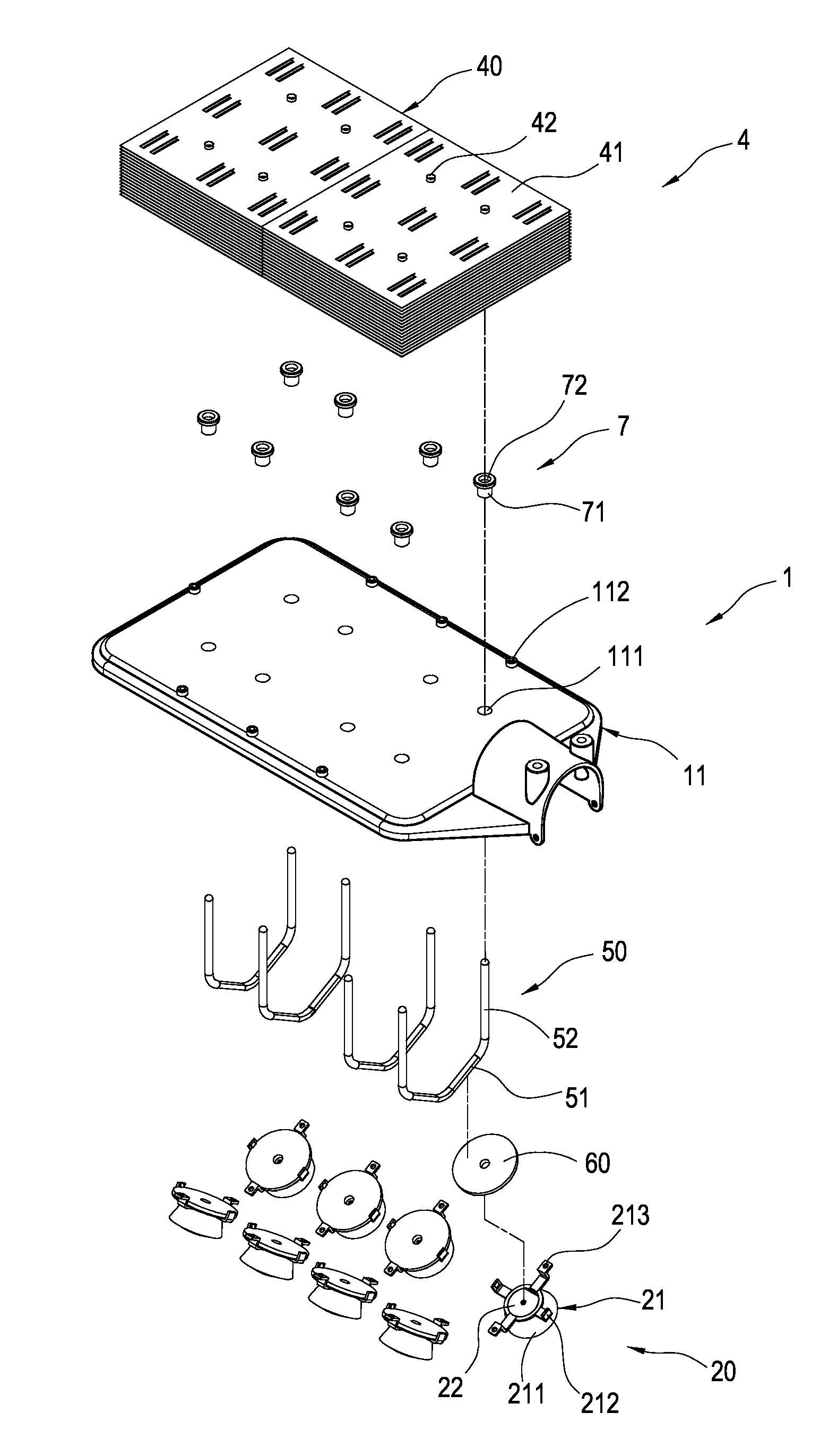
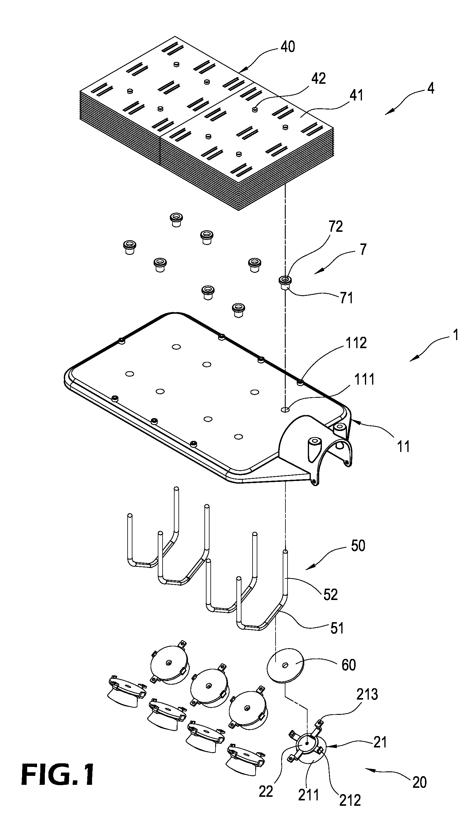
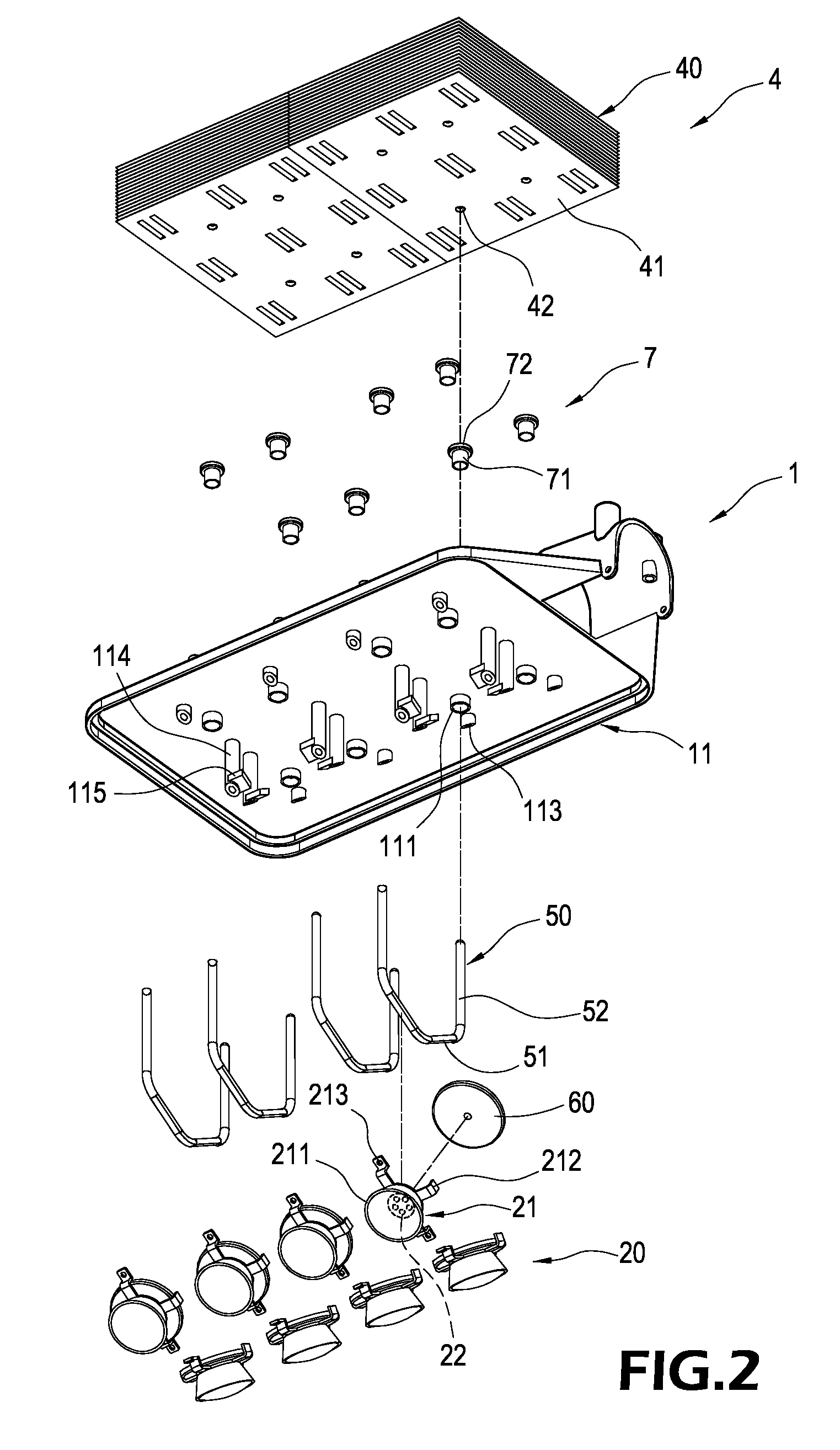
[0019]Referring to FIGS. 1 to 4 for an exploded view of a portion of the invention, another exploded view of a portion of the invention, a cross-sectional enlarged view of an assembly of the invention, and another cross-sectional enlarged view of an assembly of the invention respectively, an assembling structure for LED road lamp and heat dissipating module in accordance with the present invention comprises an LED road lamp 1 and a heat dissipating module 4.

[0020]The LED road lamp 1 comprises a rectangular partition board 11, an upper casing 12 covered onto the top of the partition board 11 and forming a containing space (also refer to FI...


PUM


Abstract

In an assembling structure for LED road lamp and heat dissipating module, the LED road lamp includes a partition board, an upper casing, a light transmitting lens and an LED lamp set. The upper casing and the light transmitting lens are set separately on upper and lower sides of the partition board. Each LED lamp set is contained in a space enclosed by the partition board and the light transmitting lens. The partition board has a plurality of through holes, and the LED lamp set includes a frame body and an LED module. The heat dissipating module includes a heat dissipating body, a heat pipe and an isothermal board. The heat dissipating body is set in a space enclosed by the partition board and the upper casing, and the heat pipe has a heat discharging end passing through and connecting the partition board and the heat dissipating body and a heat receiving end forming the bottom of the partition board. The isothermal board is fixed onto a frame body of the LED lamp and has two planes separately attached onto the heat receiving end and the LED module, so as to significantly enhance the overall heat conducting and dissipating performance, drive an LED to emit light at a lower temperature, and extend the life expectancy of the LED.

Description

BACKGROUND OF THE INVENTION[0001]1. Field of the Invention[0002]The present invention relates to an assembling structure for LED road lamp and heat dissipating module, and more particularly to an assembling structure capable of improving the heat conduction and dissipation of an LED road lamp significantly.[0003]2. Description of Prior Art[0004]Since light emitting diodes (LEDs) feature the advantages of high brightness, power saving and long life expectancy, LEDs have been used extensively for the illumination of lamps. Several LEDs are usually connected with each other to form an LED module, and a plurality of LED modules are connected in series or in parallel to constitute an LED lamp set to achieve an illumination effect that meets the requirements for a large projecting area and a high brightness and for outdoor illuminations. Since the outdoor illumination devices are exposed to the outside, therefore its requirements for airtightness, water resistance, dust resistance, and he...

Claims


Application Information

Patent Timeline
IPC IPC(8): F21V29/00H01L23/34
CPCF21V29/004F21V29/2212F21V29/83F21V29/717F21V29/767F21V29/006F21K9/00F21W2131/103F21Y2101/02Y02B20/72F21S8/086F21V29/51F21V29/71F21Y2115/10
Inventor WANG, PEI-CHOA
Owner PYROSWIFT HOLDING CO LIMITED
Learn More