Cooling structure for motorized roller

a cooling structure and motor technology, applied in the direction of lighting and heating apparatus, transportation and packaging, gearing, etc., can solve the problems of increasing the number of components, the heat generated by the motor mb, and the size increase (particularly in the radial direction), and achieves simple construction, reduced temperature increase, and easy movement of air in the axial direction.

Inactive Publication Date: 2008-02-12
SUMITOMO HEAVY IND LTD
View PDF10 Cites 18 Cited by
  • Summary
  • Abstract
  • Description
  • Claims
  • Application Information

AI Technical Summary

Benefits of technology

[0019]In order to solve the problems described above, it is an object of the present invention to provide a cooling structure for a motorized roller that is of simple construction, and is capable of effectively reducing temperature increases inside the apparatus.

Problems solved by technology

This means that size increases (particularly in the radial direction) are unavoidable, and that the number of components increases.
However, as a result of making the conventional motorized roller MR2 more compact in the radial direction, the spacing S1 between the roller body 50 and the casing 70 decreases, and because one end 70a of the casing 70 is closed, heat generated by the motor M2 and the reducer R2 tends to become trapped inside the motorized roller MR2, meaning the inside is prone to increase in temperature.
Furthermore, introducing an oil coolant into the motorized roller MR2 could be considered as one method of achieving cooling, but this would require measures to prevent problems such as oil leakage, and would not only make the structure more complex, but would also increase the number of structural restrictions in designing.

Method used


Image

  • Cooling structure for motorized roller
  • Cooling structure for motorized roller
  • Cooling structure for motorized roller

Examples


Embodiment Construction

[0034]An embodiment of the present invention will now be described in detail hereinafter with reference to the drawings.

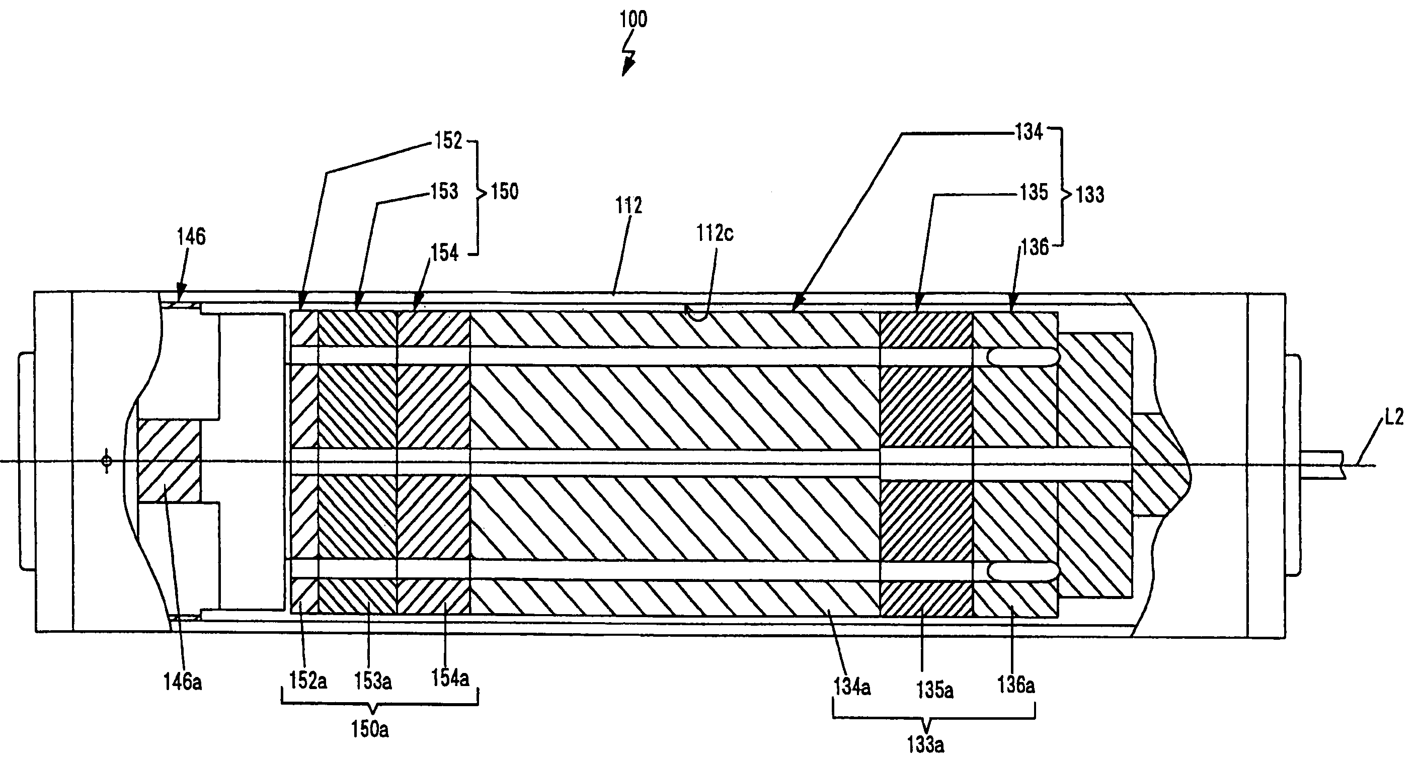
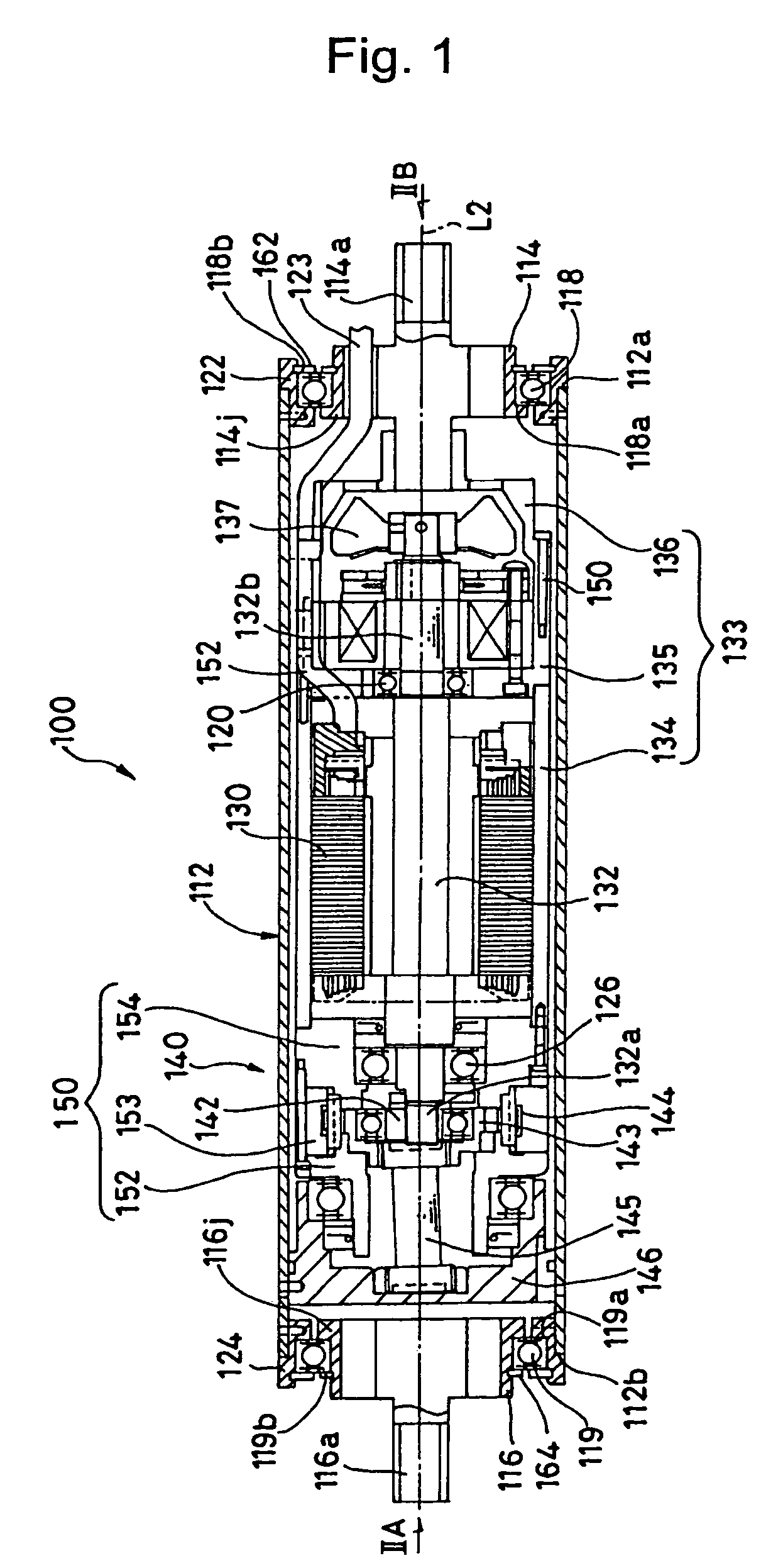
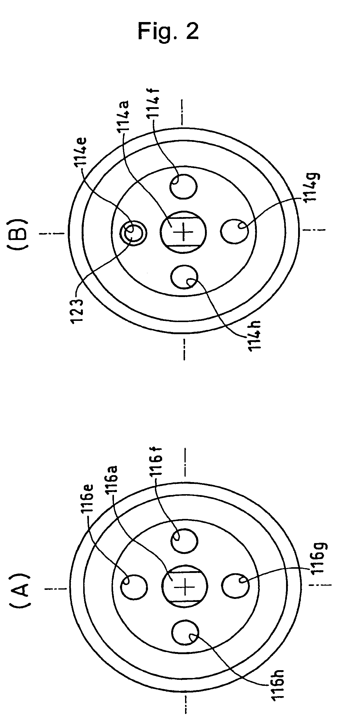
[0035]FIG. 1 and FIGS. 2(A) and 2(B) are diagrams showing a motorized roller 100 according to the embodiment of the present invention, wherein FIG. 1 is a side sectional view of the motorized roller 100 which corresponds with the view of the conventional roller shown in FIG. 7, and FIGS. 2(A) and 2(B) are side views shown along the arrow directions IIA and IIB in FIG. 1, respectively.

[0036]This motorized roller 100 comprises a motor 130 and a reducer 140 disposed inside a roller body 112, and the rotation of the motor 130 is reduced by the reducer 140 and transmitted to the roller body 112.

[0037]The roller body 112 is a substantially circular cylindrical member, and the motor 130 and the reducer 140 are both housed inside this roller body 112. Furthermore, bearings 118 and 119 are disposed at both end sections 112a and 112b of the roller body 112, with ring shaped ...


PUM


Abstract

A cooling structure for a motorized roller is provided, which has a simple construction, and is capable of effectively reducing temperature increases inside the apparatus. Such a motorized roller includes a motor and a reducer which are disposed inside a roller body. Rotations of the motor are reduced by the reducer and transmitted to the roller body, and a reaction force to the driving force of the roller body is able to be received, via casings that house the motor and the reducer, by an external member that fixes the casings so that rotations of the casings are prevented. In this cooling mechanism for the motorized roller, an air passage for guiding air in an axial direction from one end of the reducer to the other end is formed in an outer peripheral surface of the casing for the reducer.

Description

BACKGROUND OF THE INVENTION[0001]1. Field of the Invention[0002]The present invention relates to a motorized roller such as a motor pulley or a motor roller used in a conveyor or the like, and more particularly to a cooling structure for a motorized roller that has a simple construction, and is capable of effectively reducing temperature increases inside the apparatus.[0003]2. Description of the Related Art[0004]Motorized rollers have been proposed in a variety of configurations (for example, see Japanese Patent Laid-Open Publication No. 1999-127556). The proposed motorized roller is configured in such a manner that a motor and a reducer are disposed inside a roller body, and the rotation of the motor is reduced by the reducer and then transmitted to the roller body so that when fixed to an external member the roller body is able to rotate. As shown in FIG. 4, this type of motorized roller can be used as a motor roller MR for moving a package 4 placed on top of a conveyor 2 through ...

Claims


Application Information

Patent Timeline
Patent Type & Authority Patents(United States)
IPC IPC(8): F28F5/02B65G23/08F16H1/32H02K9/16H02K7/10H02K9/06
CPCB65G23/08F16H57/0415H02K7/1016H02K9/06F16H1/32
Inventor UMEDA, KAZUYOSHI
Owner SUMITOMO HEAVY IND LTD
Why Eureka
Try Eureka