
Universal filter base and engines using same

Active Publication Date: 2008-02-12
CATERPILLAR INC
View PDF16 Cites 4 Cited by
  • Summary
  • Abstract
  • Description
  • Claims
  • Application Information

AI Technical Summary

Benefits of technology

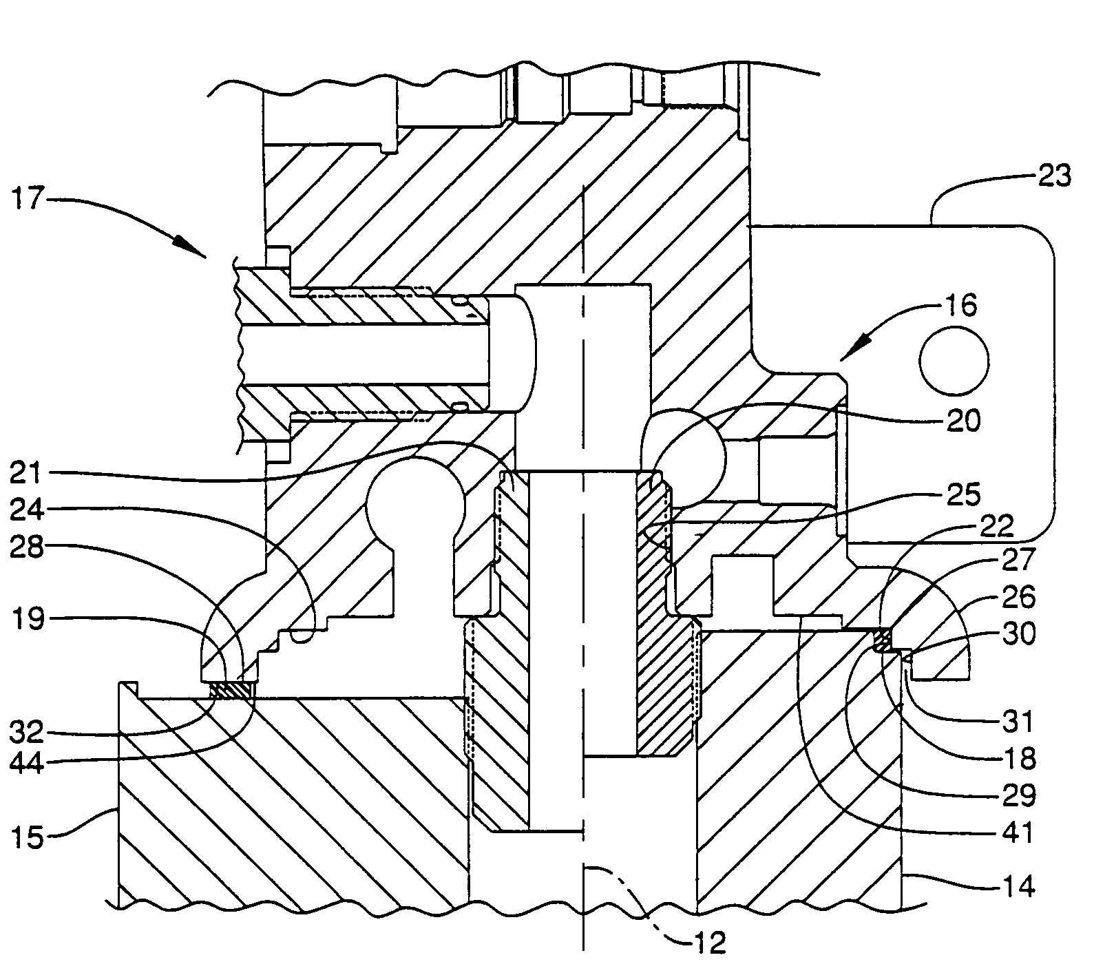
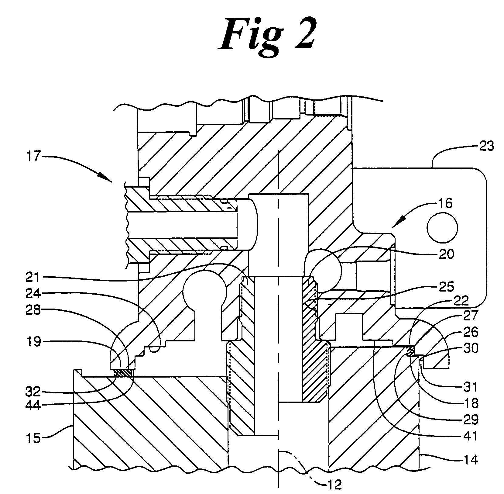
[0033]The present invention is advantageous because it provides one filter base 23 and 123 that can accept multiple fuel filters 14 and 15, or 14 and 115 by providing multiple sealing surfaces 27 and 28, or 28 and 128, respectively. The fuel filters 14, 15, 114 include different sized diameters and / or types of seals. Thus, the customer and / or manufacturer has a choice as to the size of filter and type of seal to use within the engine. Further, the customer and / or manufacturer can reduce the time interval between fuel filter changes by attaching the filter with the larger diameter to the fuel base 23, 123. In addition, the larger fuel filter can help assure that fuel is properly filtrated with the fuel quality is poorer than expected. Moreover, the fact that each fuel filter 14, 15, 114 with a different diameter and / or seal does not require a different fuel base is advantageous because it can reduce the number of parts to manage. For instance, less assembly lines producing filter bases would be needed. In addition, it would reduce the number of filter bases that must be carried, thereby reducing the difficulties associated with tracking various types of filter bases.

Problems solved by technology

The fact that a specific filter base must be manufactured for each diameter of a filter increases the costs of manufacturing filter bases.
In addition, the fact that a different fuel filter base must be used with each different sized fuel filter may cause inconvenience for the customer.
However, the Cunningham filter apparatus does not include a base that can accommodate filters of the same type but, with various diameters and sealing means.

Method used


Image

  • Universal filter base and engines using same
  • Universal filter base and engines using same
  • Universal filter base and engines using same

Examples


Embodiment Construction

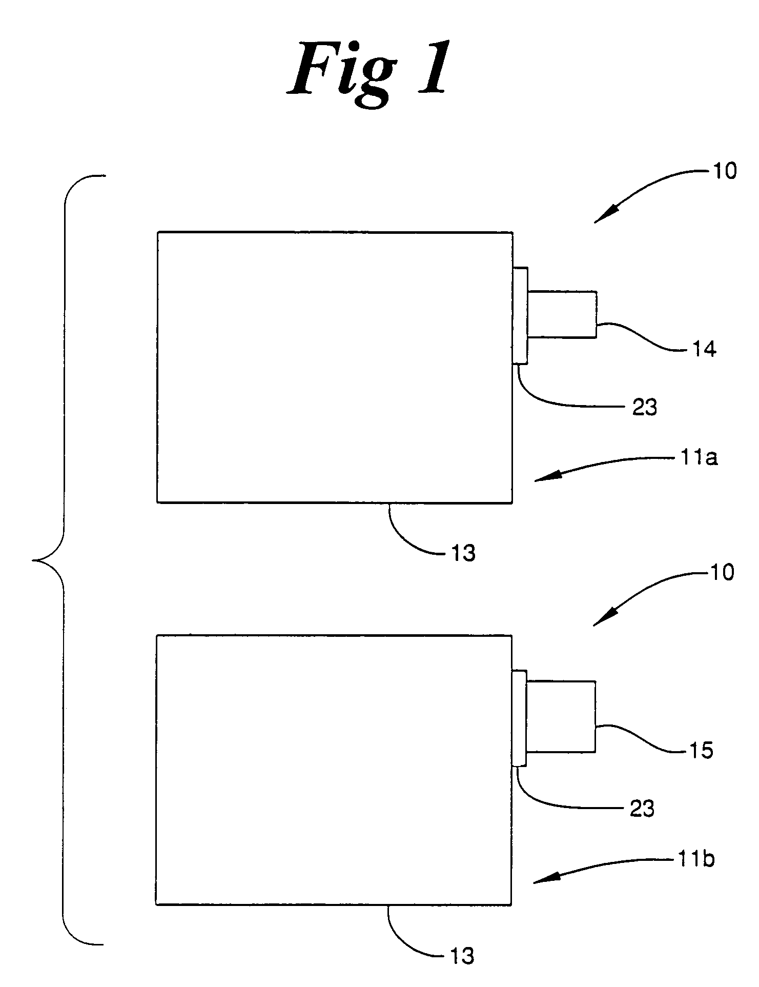
[0014]Referring to FIG. 1, there is shown a schematic representation of a group of engines 10, according to the present invention. The group of engines 10 includes a first portion 11a and a second portion 11b. Each engine within the group of engines 10 includes an engine housing 13 to which a fuel filter base 23 is attached. The filter bases 23 attached to each engine are substantially identical to one another. Further, the engines within the group of engines 10 are preferably substantially identical to one another. However, each engine within the first portion 11a includes a first filter 14 with a relatively small diameter attached to the filter base 23 and each engine within the second portion 11b includes a second filter 15 with a relatively large diameter attached to the filter base 23. Although the present invention contemplates a plurality of the engines within the group 10 including filters with diameters different than the diameters of filters 14 and 15, preferably each engi...


PUM

PropertyMeasurementUnit
Diameteraaaaaaaaaa
Sizeaaaaaaaaaa

Abstract

Filters that remove particulate and other solids from fluids often come in various sizes and include various types of seals. However, filter bases to which the filters are attached are generally manufactured to accommodate only one specific size of filter including one type of seal. A filter base of the present invention includes a filter attachment portion and a sealing portion. In order to expand the different sizes of filters that the filter base can accommodate, the sealing portion includes a first annular sealing surface with a relatively small diameter and a second annular sealing surface with a relatively large diameter. The two sealing surfaces can be any combination of radial and a face sealing surfaces. The filter base is used for filtering fluids, such as fuel, in an internal combustion engine.

Description

TECHNICAL FIELD[0001]The present invention relates generally to filter bases for internal combustion engines, and more specifically to a filter base that can accommodate filters with different sized diameters.BACKGROUND[0002]It is well known in the art to use filters of various types and sizes in order to remove particulate from fluids. For instance, most diesel fuel systems include at least one fuel filter that separates particulates and other solids from fuel prior to the fuel being injected into the engine. Typically, fuel filters include a canister in which a filter element is positioned. The filter element is comprised of a medium that traps the particulates and solids as the fuel flows though the medium. Generally, the filter is attached to a filter base that is attached to either an engine or a chassis of the vehicle or work machine. The filter may be coupled to the filter base via a threaded portion of the filter base, and a contact area between the filter base and the filte...

Claims


Application Information

Patent Timeline
IPC IPC(8): B01D35/30
CPCB01D35/30B01D35/306B01D2201/302B01D2201/304Y10S210/17
Inventor MILLAR, JAMES SUTHERLAND
Owner CATERPILLAR INC
Learn More