Supercharge Your Innovation With Domain-Expert AI Agents!

Method of fabricating a semiconductor device

a semiconductor device and manufacturing method technology, applied in semiconductor devices, semiconductor/solid-state device details, electrical devices, etc., can solve the problems of excessive polishing, inability to polish, and small film thickness region, so as to reduce the steps on the surface of copper film, reduce the cost of fabrication, and improve the throughput of semiconductor device fabrication

Active Publication Date: 2008-02-12
FUJITSU LTD
View PDF2 Cites 3 Cited by
  • Summary
  • Abstract
  • Description
  • Claims
  • Application Information

AI Technical Summary

Benefits of technology

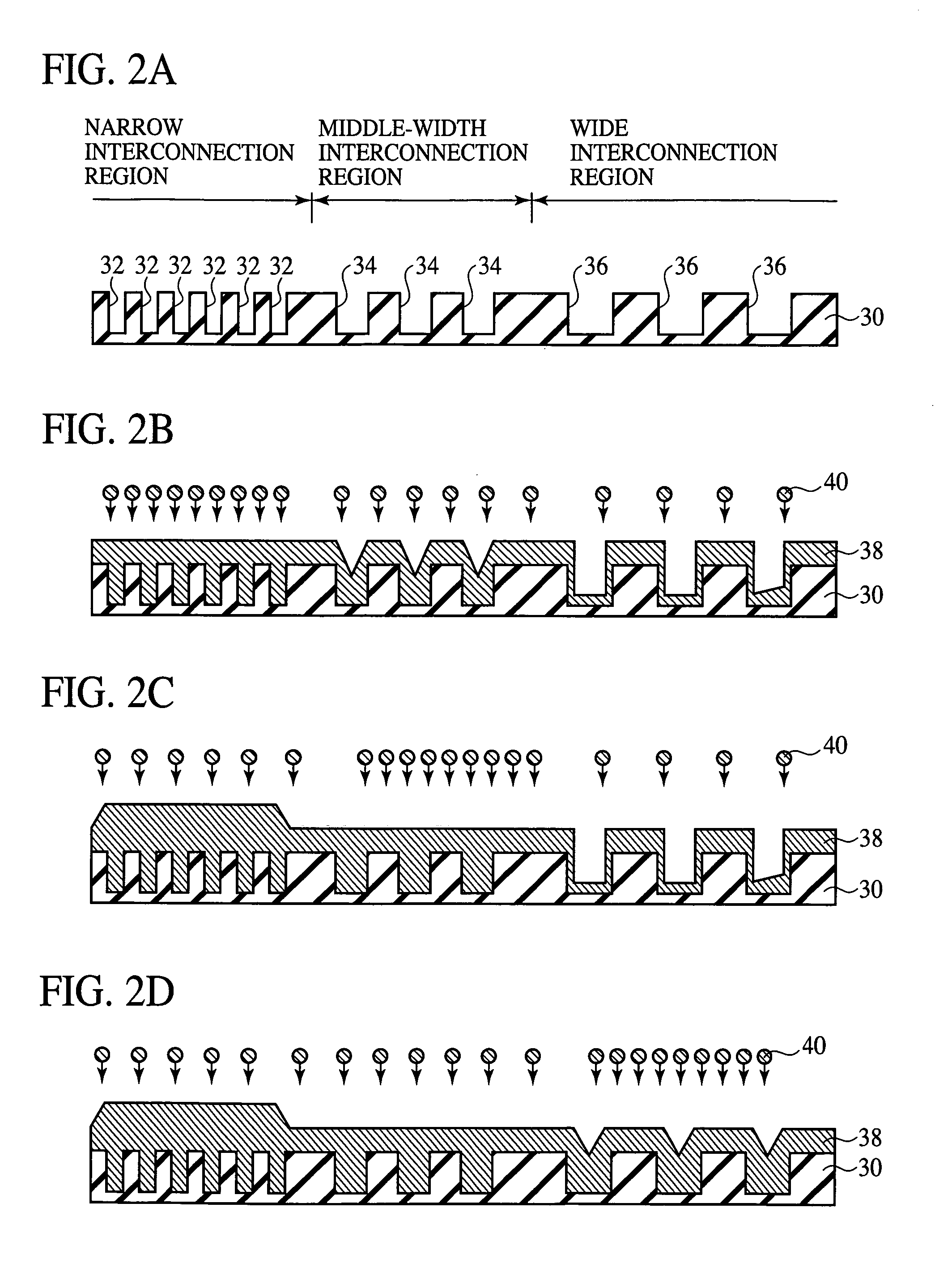
This approach decreases the steps on the copper film surface, improves fabrication throughput, and reduces fabrication costs by optimizing the copper film thickness and preventing dishing and erosion during chemical mechanical polishing.

Problems solved by technology

The step between a narrow trench / hole pattern region and a wide trench / hole pattern region becomes large, which makes the polish impossible.
That is, when the polishing amount is set for a thickest film thickness, the film in the small film thickness region, such as the wide trench and hole pattern region, is excessively polished, and dishing often takes place.

Method used


Image

  • Method of fabricating a semiconductor device
  • Method of fabricating a semiconductor device
  • Method of fabricating a semiconductor device

Examples


Embodiment Construction

[0023]The detailed growth mechanism of the bottom up growth is not clear, but factors for generating the high growth selectivity depending on the location will be additives contained in the electrolytic plating solution and their compositions. The typical additives are a brightener and an inhibitor. The former has the effects of lowering the polarization at the cathode surface to enhance growth of new crystal nuclei and also increasing the deposition rates. The latter has the effects of enhancing the polarization at the cathode surface to suppress the growth.

[0024]Then, the growth mechanism of the bottom up growth will be explained with reference to FIGS. 12A-12C.

[0025]As illustrated in FIG. 12A, a substrate having a barrier metal 104 and a seed layer 16 formed on an insulating film 100 with a trench 102 formed in is immersed in an electrolytic plating solution to expose the surface of the seed layer 106 to the brightener (indicated by “x” in FIGS. 12A-12C) and the inhibitor (indica...


PUM

PropertyMeasurementUnit
widthaaaaaaaaaa
aspect ratioaaaaaaaaaa
widthaaaaaaaaaa

Abstract

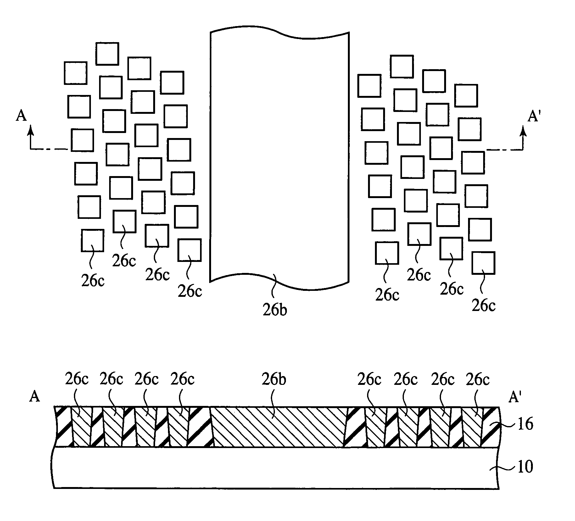
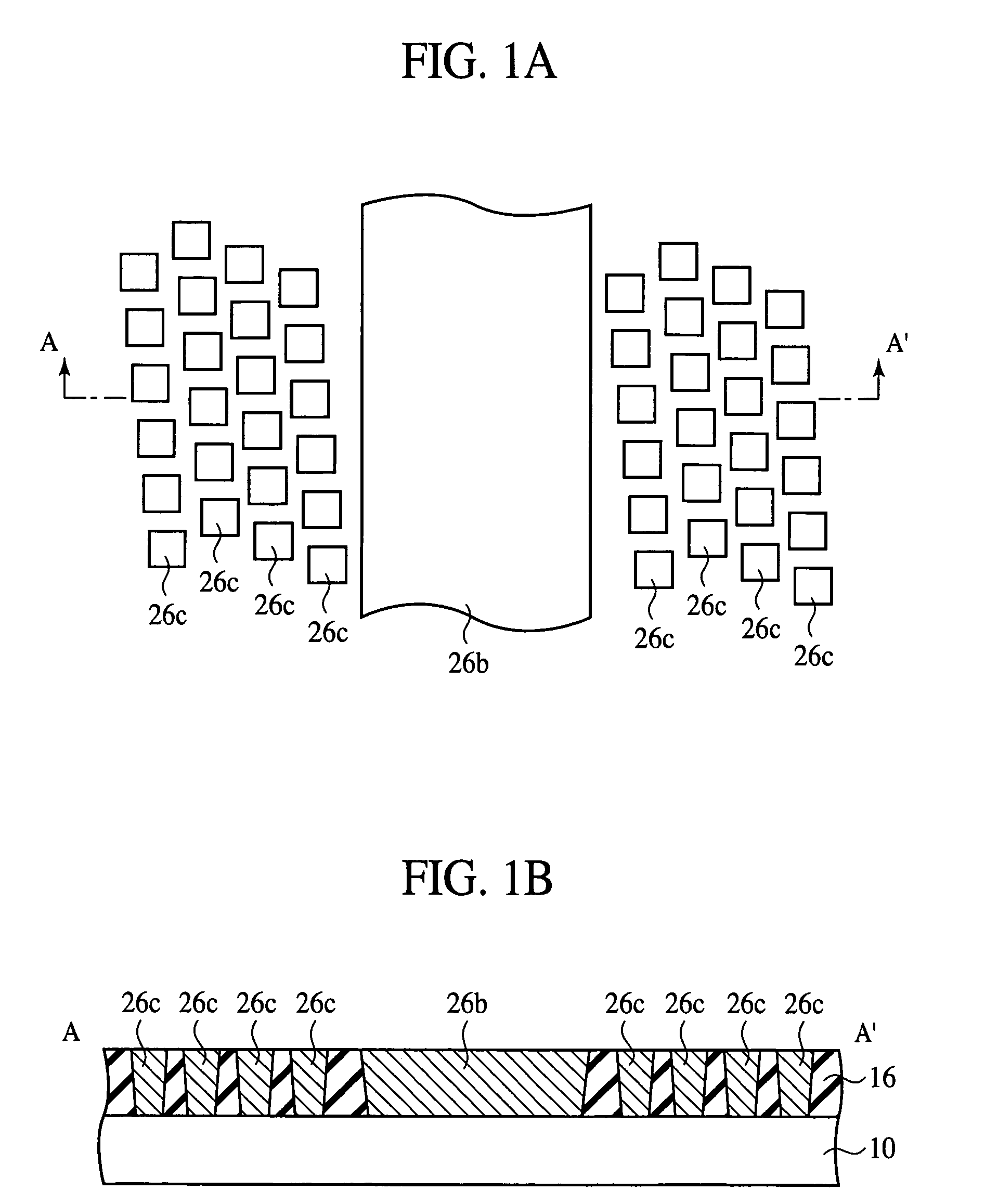
The semiconductor device comprises a copper interconnection 26b buried in an insulating film 16, and a dummy pattern for chemical mechanical polishing buried in the insulating film 16 near the copper interconnection 26b. The unit patterns 26c of the dummy pattern are formed in the density of 10-25%. Even in the case that the electrolytic plating solution for bottom up growth mechanism is used, the step on the surface of a copper film due to over-plating can be decreased, and the total plating thickness necessary to fill the interconnection trenches can be decreased.

Description

CROSS-REFERENCE TO RELATED APPLICATIONS[0001]This application is based upon and claims the benefit of priority from the prior Japanese Patent Application No. 2004-121428, filed on Apr. 16, 2004, the entire contents of which are incorporated herein by reference.BACKGROUND OF THE INVENTION[0002]The present invention relates to a semiconductor device and a method for fabricating the same, more specifically a semiconductor device including copper interconnections formed by damascene process and a method for fabricating the semiconductor device.[0003]Recently, as an interconnection material of semiconductor devices, copper, which has low resistivity and high electromigration resistance, is noted. Conventionally, interconnections of the semiconductor devices have been formed by depositing interconnection materials and then patterning by photolithography and dry etching. However, it is difficult to dry etch copper, which generates no volatile products. Then, in forming copper interconnecti...

Claims


Application Information

Patent Timeline
Patent Type & Authority Patents(United States)
IPC IPC(8): H01L23/52C25D7/12H01L21/288H01L21/304H01L21/3205H01L21/44H01L21/4763H01L21/768
CPCH01L21/7684H01L21/76877H01L21/2885
Inventor KITADA, HIDEKISHIMIZU, NORIYOSHI
Owner FUJITSU LTD
Features
  • R&D
  • Intellectual Property
  • Life Sciences
  • Materials
  • Tech Scout
  • Unparalleled Data Quality
  • Higher Quality Content
  • 60% Fewer Hallucinations
Learn More