Method and apparatus for quiet variable motor speed control

a technology of quiet variable motor and control method, which is applied in the direction of motor/generator/converter stopper, electric motor control, dynamo-electric converter control, etc., can solve the problems of mechanical and acoustic noise generated by the fan motor, annoying and distracting, and the technique that has been used in the past has serious disadvantages, and achieves full speed operation of the motor

Active Publication Date: 2008-02-12
LUTRON TECH CO LLC
View PDF55 Cites 1246 Cited by
  • Summary
  • Abstract
  • Description
  • Claims
  • Application Information

AI Technical Summary

Problems solved by technology

A problem with known controllers for fan motors is that some of the techniques that have been used in the past have serious disadvantages.
Although the prior art fan speed control 10 provides a substantially fully variable speed control, a problem with this circuit is that when a fan motor is controlled by the phase angle technique, mechanical and acoustic noises may be generated in the fan motor, which can be annoying and distracting. FIG. 1B shows the waveforms of the AC input line voltage 30A, the motor voltage 30B applied to the fan motor by the switch, and the motor current 30C through the fan motor.
However, this does not allow continuous or fully or near fully variable speed control.
Additional capacitors and switches can be provided to obtain more discrete speed levels, but the circuitry becomes unnecessarily complex, large, and expensive as more components are added.
Although this prior art system provides for a quiet fan speed control, it suffers from the drawback that the speeds are not able to be controlled continuously or fully variably or even near fully variably.

Method used


Image

  • Method and apparatus for quiet variable motor speed control
  • Method and apparatus for quiet variable motor speed control
  • Method and apparatus for quiet variable motor speed control

Examples


second embodiment

[0062]FIG. 8 shows a simplified circuit diagram of a fan speed control 80 according to the present invention. The fan speed control 80 includes a capacitor 82 in parallel with the shunt switch 54. A bypass switch 84 is connected in series with the capacitor 82 and is controlled by a control circuit 86 to selectively remove the capacitor 82 from the circuit of the fan speed control 80. The capacitor 82 preferably has a capacitance of 4.7 μF.

[0063]When the switch 84 is open, the fan speed control 80 operates in the same manner as the fan speed control 50 of FIG. 2. However, when the switch 84 is closed, the capacitor 82 is connected in parallel with the fan motor 42 and provides a path for high frequency currents to flow to neutral. The capacitor 82 acts as a filter by eliminating high frequency components in the motor voltage across the fan motor 42, which further reduces audible noise created by the fan motor.

[0064]If the full speed of the fan motor 42 is desired, the switch 58 is c...

third embodiment

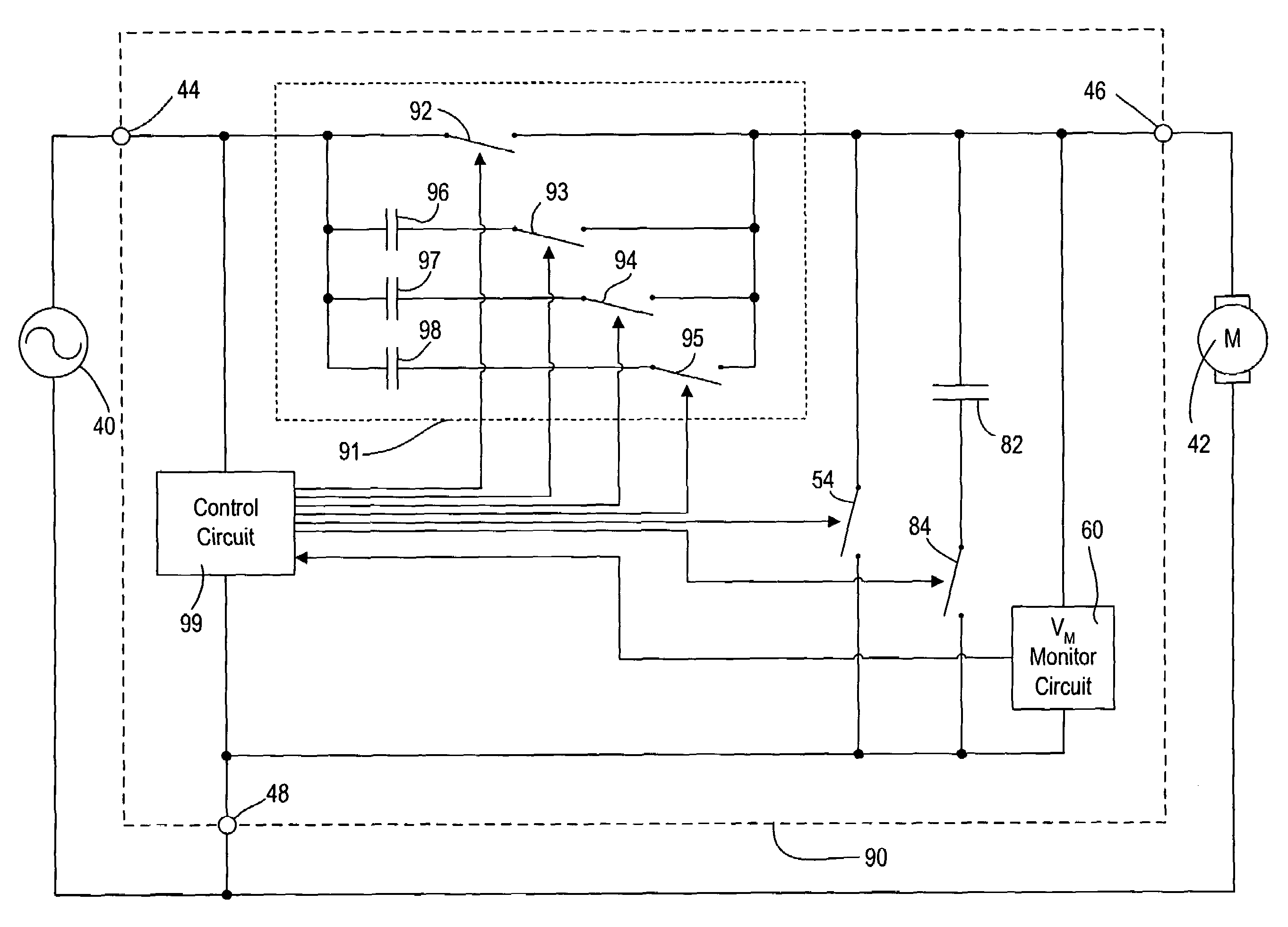
[0065]FIG. 9 shows a simplified circuit diagram of a fan speed control 90 according to the present invention. The fan speed control 90 includes a switched capacitor network 91 in series with the terminals 44, 46. The switch capacitor network 91 comprises a plurality of switches 92, 93, 94, 95, each separately controlled by a control circuit 99. Three of the switches 93, 94, 95 are each connected in series with one of three capacitors 96, 97, 98, respectively.

[0066]The fan speed control 90 offers three different modes of operation to drive the fan motor 42. The first mode of operation (referred to herein as “120 Hz AC buck” mode) functions in a similar manner as the fan speed control 80 of FIG. 8. In this mode, one of the switches of the switched capacitor network 91 (for example, the switch 93) is constantly closed such that one of the series capacitor (for example, the capacitor 96) is in series with the terminals 44, 46. While the control circuit 99 maintains the switch 84 closed,...


PUM


Abstract

An apparatus for controlling the speed of an AC motor comprising a switch adapted to be coupled in parallel with power terminals for the AC motor; a capacitor coupled in series with the parallel combination of the switch and the motor; the capacitor adapted to provide an AC supply voltage from an AC source to the parallel circuit comprising the motor and the switch; and a control circuit for controlling the conduction time of the switch in order to vary the speed of the motor. The switch is preferably pulse-width modulated at a frequency twice the line frequency of the AC supply voltage, and the switch is turned on when the voltage across the AC motor is zero volts. The apparatus is operable to provide for continuously variable control of the motor speed while minimizing acoustic noise in the motor.

Description

RELATED APPLICATIONS[0001]This application claims priority from commonly-assigned U.S. Provisional Application Ser. No. 60 / 687,828, filed Jun. 6, 2005, having the same title as the present application, the entire disclosure of which is hereby incorporated by reference.BACKGROUND OF THE INVENTION[0002]1. Field of the Invention[0003]The present invention relates to load control devices for providing variable power to alternating-current (AC) loads, for example, motor loads, and more particularly, to AC fan motors. More particularly, the invention relates to a quiet variable fan speed control, which allows substantially full variability in the fan speed control.[0004]2. Description of the Related Art[0005]A problem with known controllers for fan motors is that some of the techniques that have been used in the past have serious disadvantages. For example, fully variable fan speed controls are known. FIG. 1A shows a prior art fully variable fan speed control 10 in which a switch 12, typi...

Claims


Application Information

Patent Timeline
Patent Type & Authority Patents(United States)
IPC IPC(8): H02K27/00
CPCH02P25/04H02P25/14H02P27/16H02P29/0038H02P29/50Y02B30/70
Inventor DEJONGE, STUARTSTEINER, JAMES PDOBBINS, AARONWU, CHEN MING
Owner LUTRON TECH CO LLC
Why Eureka
Try Eureka