Direct current cutoff switch

a cutoff switch and current technology, applied in protective switch details, relays, positive temperature coefficient thermistors, etc., can solve the problems of circuit short circuit, surge voltage, contact melting due to surge voltage, etc., and achieve the effect of extending use and preventing contact melting

Active Publication Date: 2008-02-12
UCHIYA THERMOSTAT
View PDF11 Cites 46 Cited by
  • Summary
  • Abstract
  • Description
  • Claims
  • Application Information

AI Technical Summary

Benefits of technology

[0026]The non-linear resistor is provided between the fixed contact or the movable contact and the above-mentioned connection terminal unit, for example, and an arc generated between contacts at the time of the opening of the movable contact is prevented from continuing for two or more milli-seconds.
[0028]As described above, according to the present invention, since a PTC whose voltage / current characteristic and temperature characteristic are especially set is parallel connected to the contact circuit of the switch, a closed circuit is formed and it is difficult for surge voltage to occur even if high-voltage current is cut off by opening the contacts of the switch. Then, the PTC passes through the minimum resistance area to complete the current cutoff operation. Thus, direct current with 30V through 50V or higher voltage of 130V through 310V can be rapidly and certainly cut off without setting a distance between contacts to be opened wide. Accordingly, the miniaturization of a switching mechanism can be realized, the recent miniaturization of electronic equipment can be easily realized and its usage can be extended, which is convenient.
[0029]Since no arc occurs between contacts, the contacts can be prevented from melting. Accordingly, a highly-reliable long-life high-voltage direct current cutoff switch can be provided.

Problems solved by technology

The switch of the above-mentioned conventional current circuit has one problem, which is the melting of contacts due to surge voltages.
This is because high surge voltage occurs if such high voltage / large current is cut off.
As a result, the circuit is short-circuited by melting the contacts and generating fusion between the contacts.
Alternatively, even if the contacts are maintained open, a dielectric member around the contacts often melts down, produces smoke or fires by heat, which is a problem.
Therefore, the problem of contact meltdown cannot be solved.
However, the value of a resistor sufficient to reduce current so as to prevent or suppress sparks is very low.
If such a low resistance value is connected even after the contacts are opened, the accumulated amount of leak current becomes too large to neglect and uneconomical.
However, any of these devices is used to protect circuits driven by the above-mentioned voltage in use from abnormal surge voltage by absorbing high surge voltage at the time of an emergency, and are different from voltage in use, and are not used to absorb surge voltage that is almost the same as voltage used at the time of the opening / closing of a switch.
That is, the surge device cannot fulfill a function to absorb surge voltage, since surge voltage at the time of the opening / closing of the switch is almost the same as the voltage in use.
Since generally a surge voltage absorbing device absorbs surge voltage by reducing a resistance value by self-heating, when using higher voltage, if far higher excessive voltage is applied, in the worst case, thermal runaway occurs and self-destruction is caused.

Method used


Image

  • Direct current cutoff switch
  • Direct current cutoff switch
  • Direct current cutoff switch

Examples


Embodiment Construction

[0077]The preferred embodiments of the present invention are described below with reference to the drawings. The direct current cutoff switch of the present invention embeds a PTC with a special characteristic, which is described later.

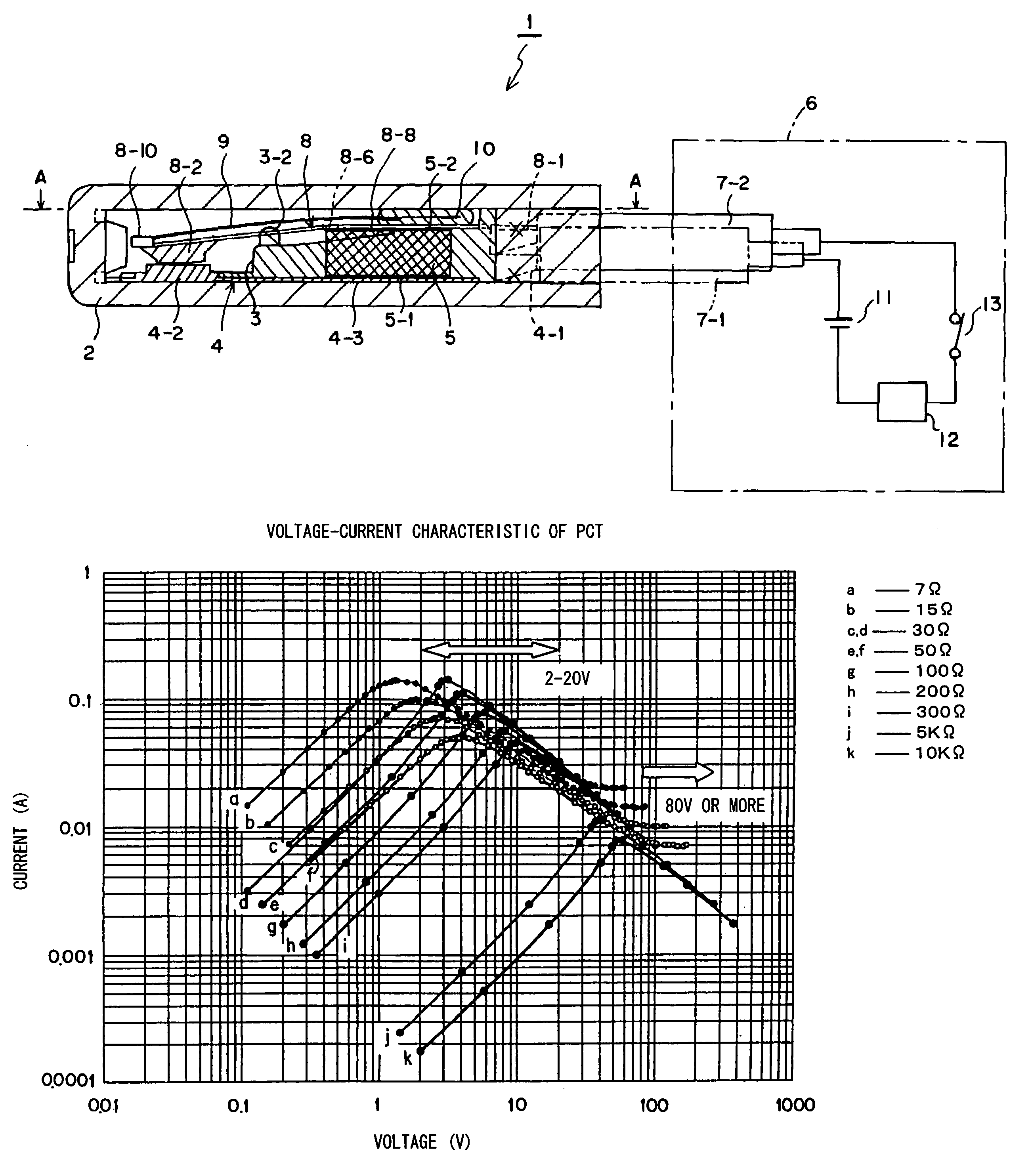
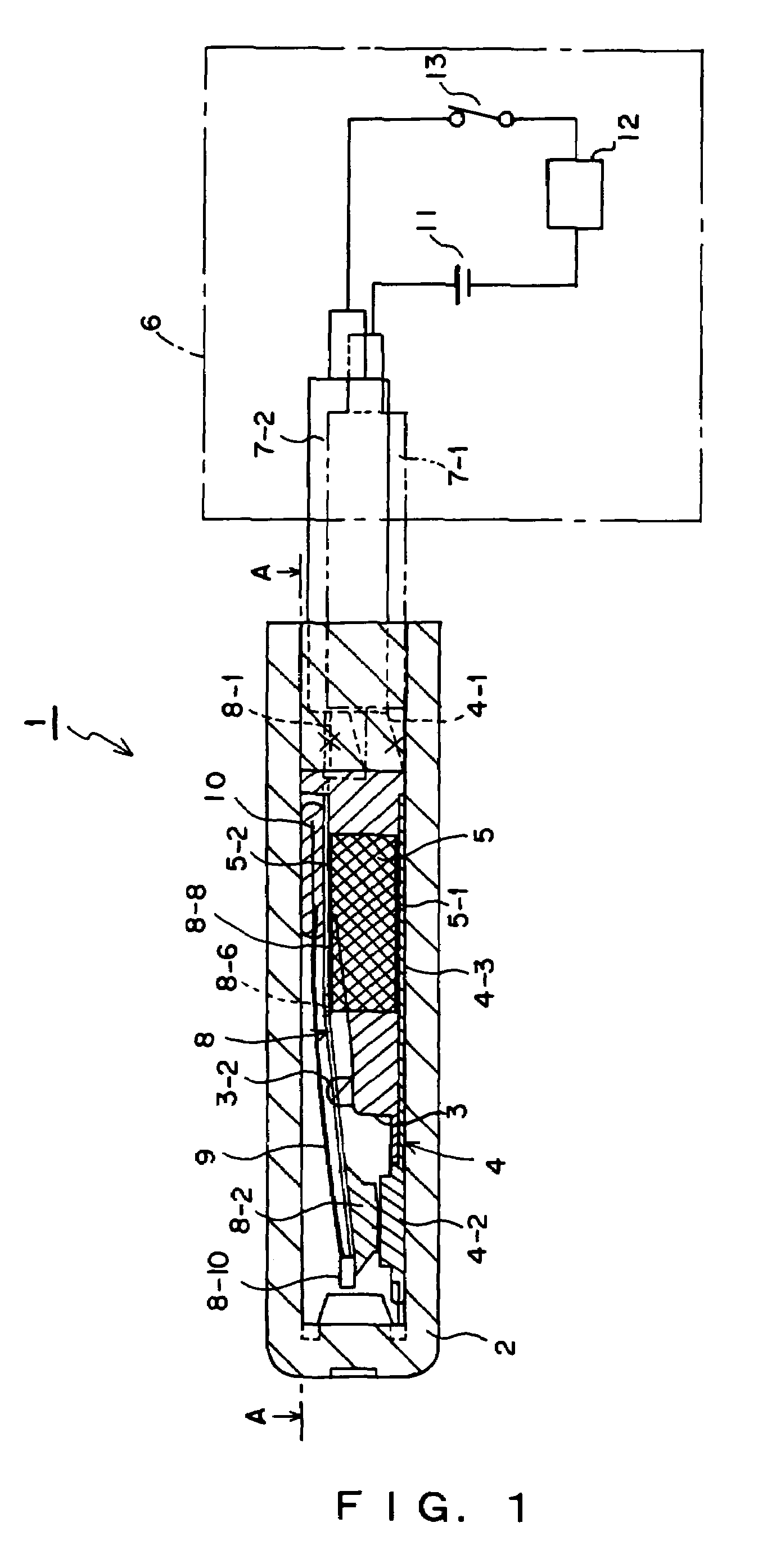
[0078]FIG. 1 shows the sectional side view of a thermostat as the direct current cutoff switch in one preferred embodiment of the present invention and an external circuit connected to this thermostat.

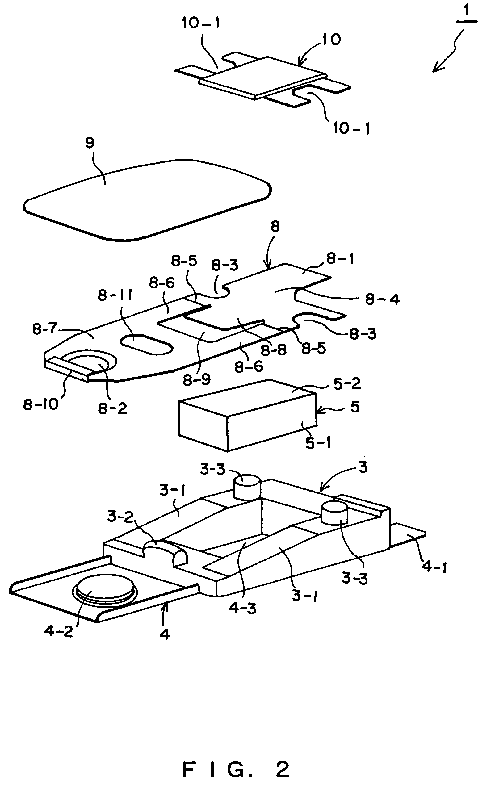
[0079]FIG. 2 is an exploded perspective illustration showing the internal structure of the thermostat.

[0080]As shown in FIGS. 1 and 2, first, a thermostat 1 comprises a housing 2, a frame-shaped support member 3 fixed on one inner wall surface of the housing and a fixed plate 4 as an inductive fixed member inserted between the base of the support member and the inner wall surface of the housing 2. In the frame of the support member 3, a quadrangular prism-shaped PTC 5 as a non-linear resistor is accommodated.

[0081]The shape of this PTC 5 is not limited t...


PUM


Abstract

In a direct current cutoff switch1, a PTC 5, which is a non-linear resistor, is parallel connected to a contact circuit composed of a fixed contact 4-2 and a movable contact 8-2 via electrodes 5-1. When the switch is closed, no current flows in the PTC 5 with a prescribed resistance value at 25° C., since voltage between both the electrodes 5-1 is almost “0”. When the switch is opened in order to cut off current, the contacts form a closed circuit since the PTC 5 is parallel inserted between the fixed contact 4-2 and the movable contact 8-2. For this reason, it is difficult for surge voltage to occur and an arc hardly occurs between both the contacts. The PTC 5 instantaneously heats due to passing current, reduces the resistance value and passes peak current. Then, the resistance value rises and becomes stable in a high value such that weak current which is negligible at 42V, which is rated voltage. Thus, current is substantially cut off.

Description

TECHNICAL FIELD[0001]The present invention relates to a direct current cutoff switch, more particularly to a direct current cutoff switch for preventing contacts from melting by reducing the occurrence time of the contact-opening arc of a high-voltage current circuit and reducing its damage.BACKGROUND ART[0002]There is conventionally a switch used for the opening / closing of a direct current circuit in the electrical equipment of automobiles, and electronic products driven by a battery or the like. Power supply voltage for driving the electrical equipment of the conventional automobile in which such a switch is used is mainly DC 12V or DC 24V, and power supply voltage for portable electronic equipment using a battery is also mainly DC 12V.[0003]Even motor-driven tools required to output high power can be sufficiently driven by DC 18V or 24V, and the conventional switch has been used as a switch for such a power supply unit without any modifications and without any trouble.[0004]Howev...

Claims


Application Information

Patent Timeline
Patent Type & Authority Patents(United States)
IPC IPC(8): H01H37/32H01H37/54H01C7/02H01H1/50H01H9/42H01H9/54H01H33/59H01H37/52H01H47/00H01H50/02
CPCH01H1/504H01H9/42H01H33/596H01H37/52H01H37/54H01H50/021H01H2033/163H01H2037/5481
Inventor TAKEDA, HIDEAKI
Owner UCHIYA THERMOSTAT
Why Eureka
Try Eureka