Method and apparatus for fast pore pressure measurement during drilling operations

a technology of pore pressure measurement and drilling operation, which is applied in the direction of survey, earth drilling and mining, borehole/well accessories, etc., can solve problems such as pore pressure perturbation, and achieve the effect of quaking pore pressure measurements

Active Publication Date: 2008-02-19
SCHLUMBERGER TECH CORP
View PDF33 Cites 25 Cited by
  • Summary
  • Abstract
  • Description
  • Claims
  • Application Information

AI Technical Summary

Benefits of technology

[0015]This present invention proposes a method for determining pore pressure at the mudcake-rock interface during drilling operations, which may also significantly quicken pore-pressure measurements made with wireline logging tools or logging-while-drilling (LWD) tools. In the implementation of the present invention, it is necessary to establish hydraulic communication between the formation and the apparatus tool of the present invention. This tool can be a combination of a conventional probe and an oscillator (transducer with an oscillating vibrator).

Problems solved by technology

This pore-pressure measurement method will not generate undesirable pore-pressure perturbation in the formation behind the probe interface because the confined cylinder volume filled with mud and mudcake is small.

Method used


Image

  • Method and apparatus for fast pore pressure measurement during drilling operations
  • Method and apparatus for fast pore pressure measurement during drilling operations
  • Method and apparatus for fast pore pressure measurement during drilling operations

Examples


Embodiment Construction

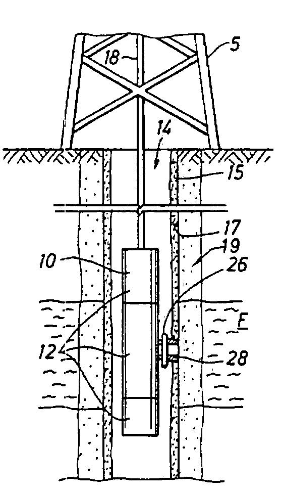
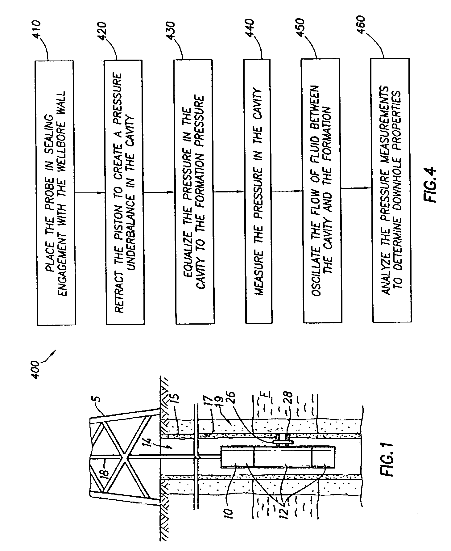
[0027]FIG. 1 depicts an example environment within which the present invention may be used. A downhole wireline tool 10 is deployable into bore hole 14 and suspended therein with a conventional wire line 18, or conductor or conventional tubing or coiled tubing, below a rig 5 as will be appreciated by one of skill in the art. The illustrated tool 10 includes a probe 28 positionable through the mudcake 15 and adjacent sidewall 17 of the borehole 14 and a surrounding formation F. An invaded zone 19 created during drilling surrounds the wellbore. The probe 28 is extended from the downhole tool using a standard extension device, typically a retractable piston.

[0028]The down hole tool 10 of FIG. 1 may be any type of wireline tool used for formation evaluation, such as the downhole tool depicted in U.S. Pat. Nos. 4,936,139 and 4,860,581 and assigned to the assignee of the present invention, the entire contents of which are hereby incorporated by reference herein in their entireties. While ...


PUM


Abstract

A method and apparatus for measuring the pressure of a formation penetrated by a wellbore is provided. A downhole tool is positioned in the wellbore and a probe is extended therefrom into sealing engagement with the formation. A piston in the probe is retracted therein where by a cavity is defined for receiving a fluid from the formation. A pressure underbalance in the cavity draws fluid from the formation into the cavity. An oscillator may be used to fluctuate the flow of fluid into the cavity. A pressure gauge is used to measure the pressure of fluid in the cavity.

Description

BACKGROUND OF INVENTION[0001]The present invention relates generally to the determination of various downhole parameters of a wellbore penetrated by a subterranean formation. More specifically, the present invention relates to techniques for determining downhole pressure during wellbore operations.[0002]In a typical wellbore operation, a downhole drilling tool drills a borehole, or wellbore, into a rock or earth formation. During the drilling process, it is often desirable to determine various downhole parameters in order to conduct the drilling process and / or learn about the formation of interest. The downhole drilling tool may be provided with mechanisms for measuring and / or monitoring such downhole parameters. To further investigate the wellbore and the downhole parameters of interest, the drilling tool is removed and a wireline tool is lowered into the wellbore to take measurements and / or to take samples. Such techniques for determining downhole parameters are sometimes referred...

Claims


Application Information

Patent Timeline
Patent Type & Authority Patents(United States)
IPC IPC(8): E21B47/06E21B49/10
CPCE21B47/06E21B49/10
Inventor ZAZOVSKY, ALEXANDER
Owner SCHLUMBERGER TECH CORP
Why Eureka
Try Eureka