Intravascular stent and method of use

a technology of intravascular stents and stents, which is applied in the field of intravascular stents, can solve problems such as arteries that may develop vulnerable plaques, and achieve the effect of high degree of vessel wall coverag

Active Publication Date: 2008-02-19
ABBOTT CARDIOVASCULAR
View PDF16 Cites 62 Cited by
  • Summary
  • Abstract
  • Description
  • Claims
  • Application Information

AI Technical Summary

Benefits of technology

[0008]The cylindrical rings and links can have various configurations. In one embodiment, each of the cylindrical rings making up the stent have a proximal end and a distal end and a cylindrical plane defined by a cylindrical outer wall surface that extends circumferentially between the proximal end and the distal end of the cylindrical ring. Each of the cylindrical rings of the proximal and distal sections includes an undulating pattern of U-shaped portions having peaks, valleys and substantially straight portions therebetween. The peaks of one ring are substantially circumferentially aligned with the peaks of an adjacent ring. At least one substantially straight link attaches one cylindrical ring to an adjacent cylindrical ring so that each substantially straight link connects one of the valleys on one ring to a valley on the adjacent ring. The links are positioned substantially within the cylindrical plane of the outer wall surface of the cylindrical rings. The design of the links and their placement provides for uniform scaffolding and a high degree of vessel wall coverage at the proximal and distal sections. Further, the cylindrical rings are configured to provide flexibility to the stent in that the portions of the rings can flex or bend and tip outwardly as the stent is delivered through a tortuous vessel.

Problems solved by technology

While some of these stents are flexible and have the appropriate radial rigidity needed to hold open a vessel or artery, there typically is a tradeoff between flexibility and radial strength.
Further, some coronary arteries may develop vulnerable plaque which may require treatment through stenting.

Method used


Image

  • Intravascular stent and method of use
  • Intravascular stent and method of use
  • Intravascular stent and method of use

Examples


Embodiment Construction

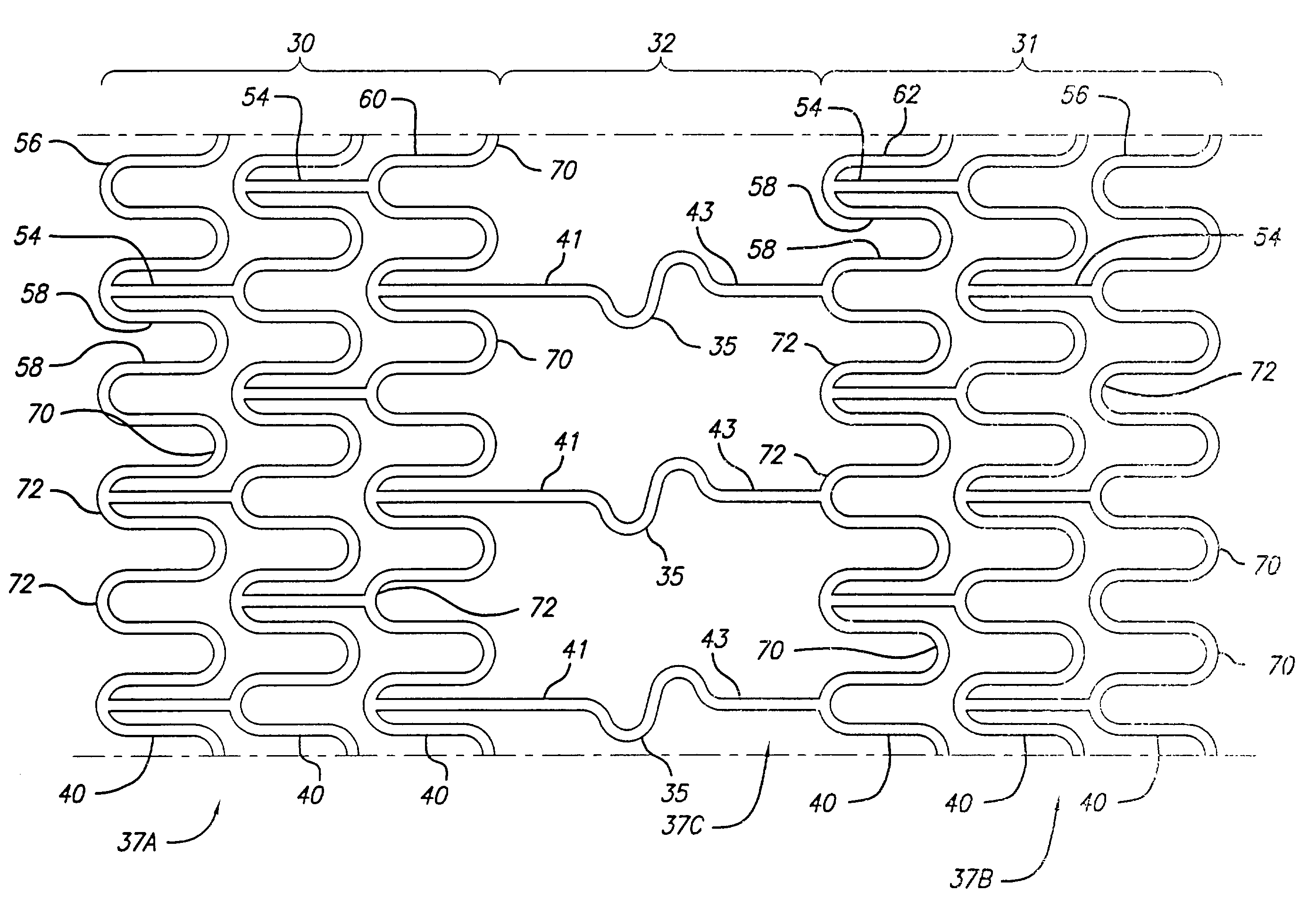
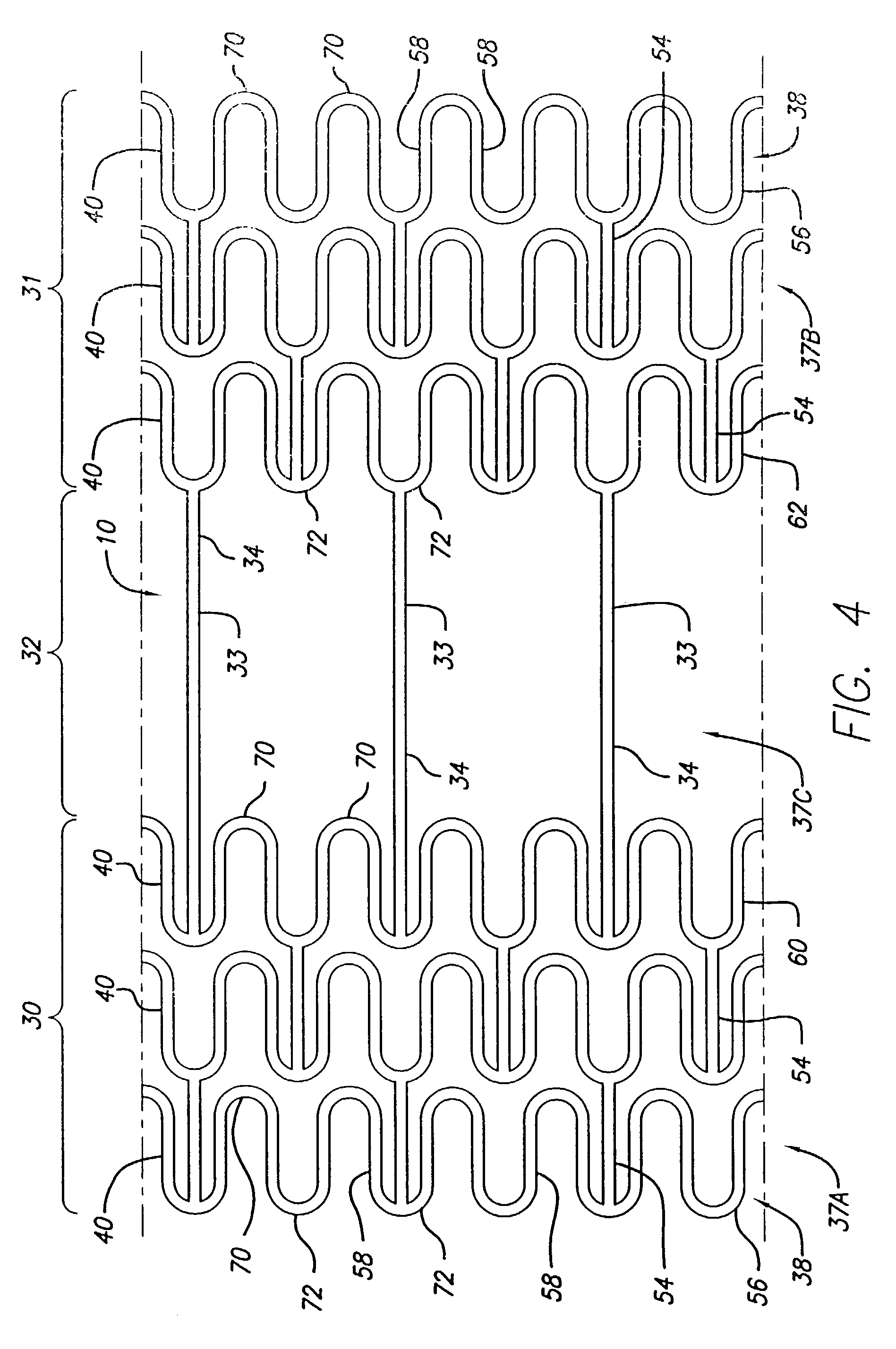
[0032]The present invention stent improves on existing stents by providing a uniquely designed pattern. The stent of the present invention provides radial rigidity and a high degree of scaffolding of a vessel wall at the stent ends and less scaffolding in the central section to intentionally promote smooth muscle cell growth over the central section. The design of the links and cylindrical rings of the distal and proximal sections provides for uniform scaffolding and a high degree of vessel wall coverage while the struts of the central section provide comparatively minimal vessel wall coverage.

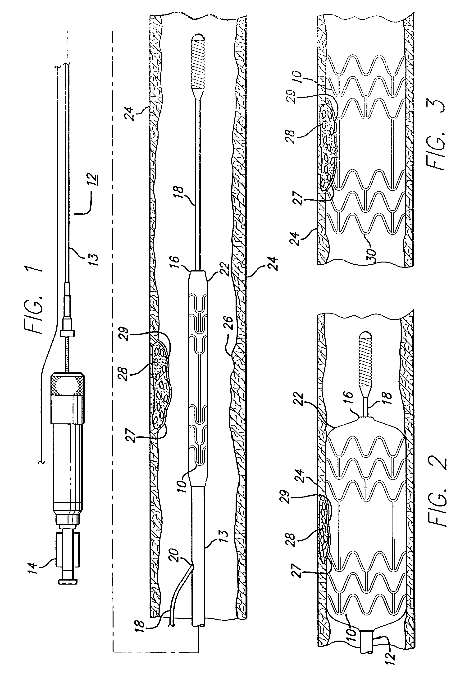
[0033]Turning to the drawings, FIG. 1 depicts the present invention stent 10 mounted on a catheter assembly 12 which is used to deliver the stent and implant it in a body lumen, such as a coronary artery, peripheral artery, or other vessel or lumen within the body. The catheter assembly includes a catheter shaft 13 which has a proximal end 14 and a distal end 16. The catheter assembly is confi...


PUM


Abstract

An expandable stent is implanted in a body lumen, such as a coronary artery, peripheral artery, or other body lumen for treating an area of vulnerable plaque. The invention provides for an intravascular stent having a plurality of cylindrical rings connected by straight links. Alternatively, the cylindrical rings of the distal section and the cylindrical rings of the proximal section are connected directly to adjacent cylindrical rings. The stent has adequate vessel wall coverage and radial strength sufficient to hold open an artery or other body lumen. A central section is positioned between distal and proximal sections and is aligned with the area of vulnerable plaque to enhance growth of cells over the fibrous cap of the vulnerable plaque to reinforce the area and reduce the likelihood of rupture.

Description

BACKGROUND OF THE INVENTION[0001]This invention relates to vascular repair devices, and in particular intravascular stents, which are adapted to be implanted into a patient's body lumen, such as a blood vessel or coronary artery, to maintain the patency thereof. Stents are particularly useful in the treatment of atherosclerotic stenosis in arteries and blood vessels.[0002]Stents are generally tubular-shaped devices which function to hold open a segment of a blood vessel or other body lumen such as a coronary artery. They also are suitable for use to support and hold back a dissected arterial lining that can occlude the fluid passageway. At present, there are numerous commercial stents being marketed throughout the world. While some of these stents are flexible and have the appropriate radial rigidity needed to hold open a vessel or artery, there typically is a tradeoff between flexibility and radial strength.[0003]Further, some coronary arteries may develop vulnerable plaque which m...

Claims


Application Information

Patent Timeline
Patent Type & Authority Patents(United States)
IPC IPC(8): A61F2/82
CPCA61F2/91A61F2/915A61F2002/825A61F2230/0013A61F2002/91558A61F2002/91575A61F2002/91525
Inventor COX, DANIEL L.
Owner ABBOTT CARDIOVASCULAR
Why Eureka
Try Eureka