Sending/receiving method, and device for the same

a technology of sending device and receiving method, applied in the field of sending and receiving data, can solve the problems of wasting bandwidth, affecting the sending of data packets by the sending device, and affecting the transmission quality of data packets, etc., and achieve the effect of stable transmission quality and stable transmission quality

Active Publication Date: 2008-02-19
APPLE INC
View PDF30 Cites 43 Cited by
  • Summary
  • Abstract
  • Description
  • Claims
  • Application Information

AI Technical Summary

Benefits of technology

[0011]In light of these conventional problems, it is an object of the present invention to perform data transmission with a stable transmission quality in a transmission path like the Internet in which there are various connection schemes and fluctuations in the transmission bandwidth (and in particular in a connection scheme with mixed wired and wireless networks, where it has conventionally been difficult to carry out data transmission with a stable transmission quality).

Problems solved by technology

The above conventional technologies have experienced various types of problems, including the following.
W-RTP and RTP / RX do not have a function for interrupting the request for retransmission even in these cases, so receiving terminals continue sending retransmission request packets, which wastes bandwidth.
With W-RTP and RTP / RX, if the sending terminal receives numerous retransmission request packets from a plurality of receiving terminals at once, then the sending terminal or the transmission path may become momentarily overloaded, which can negatively affect the sending of data packets by the sending device.
Packet loss in wired sections is caused by congestion, and thus there is the possibility that the congestion is further exacerbated by the requests for retransmission.
The cause of packet loss in wireless sections is the disposal of packets by the receiving terminal due to bit errors.
Therefore, the packet loss rate does not change even if the method for retransmission on wired sections is used and the transmission rate of the packets is lowered in accordance with the retransmission request, and the result is a continual decrease in the packet transmission rate.
However, RTP / RX does not include a method for distinguishing between packet loss in wired sections and packet loss in wireless sections.
Yet there is the possibility that errors may occur in the field indicating the packet length, and therefore the accurate reception rate cannot be determined.
Furthermore, it is not possible to determine from the send / receive rate ratio how much packet loss actually occurred in the wireless sections, so it is difficult to determine how much robustness to add (that is, determine the threshold value of the send / receive rate ratio).

Method used


Image

  • Sending/receiving method, and device for the same
  • Sending/receiving method, and device for the same
  • Sending/receiving method, and device for the same

Examples


first embodiment

[0042]The present embodiment is primarily for solving the above first problem by individually forbidding or allowing the retransmission requests of a plurality of receiving terminals for retransmission from the sending terminal.

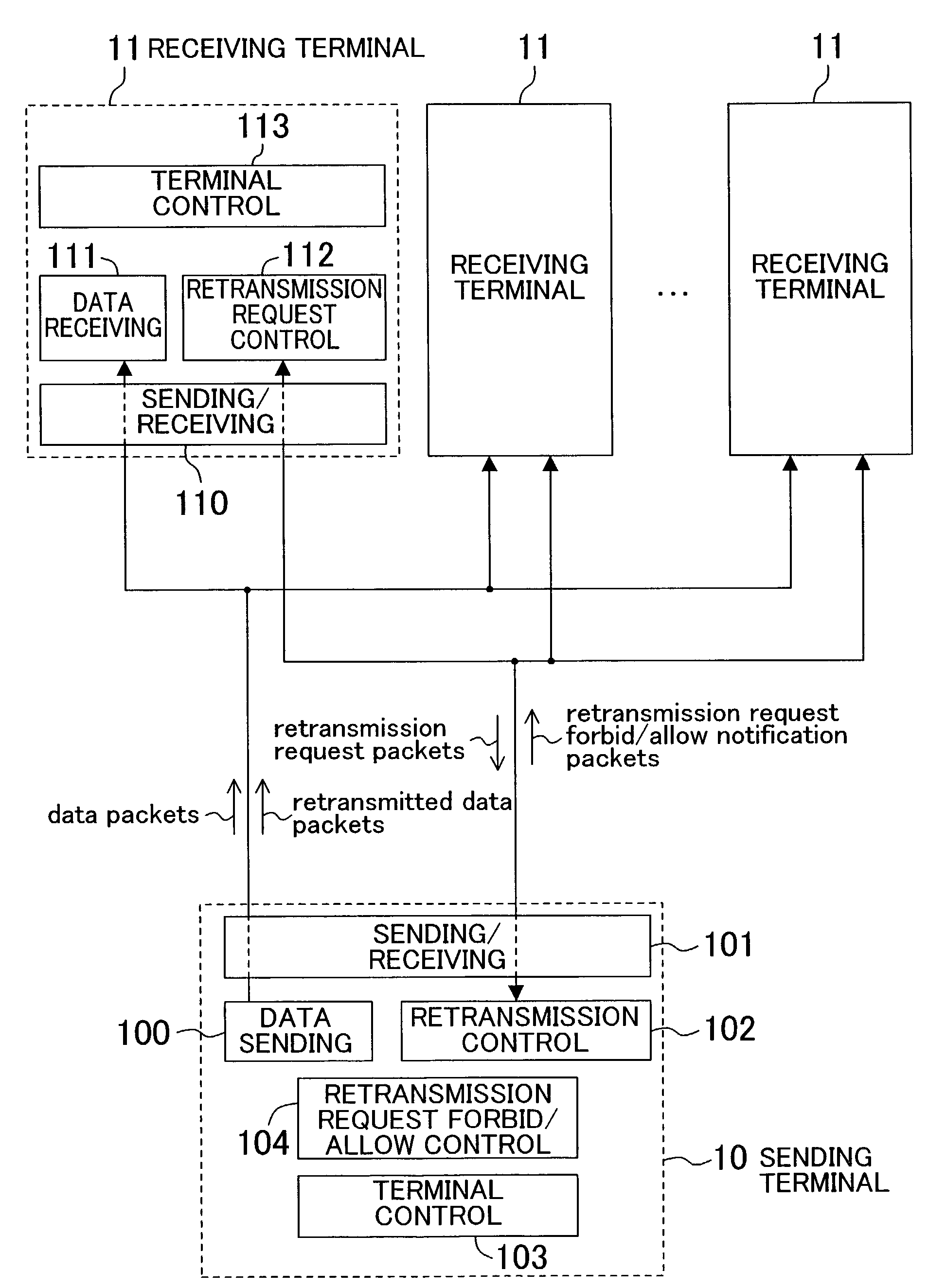
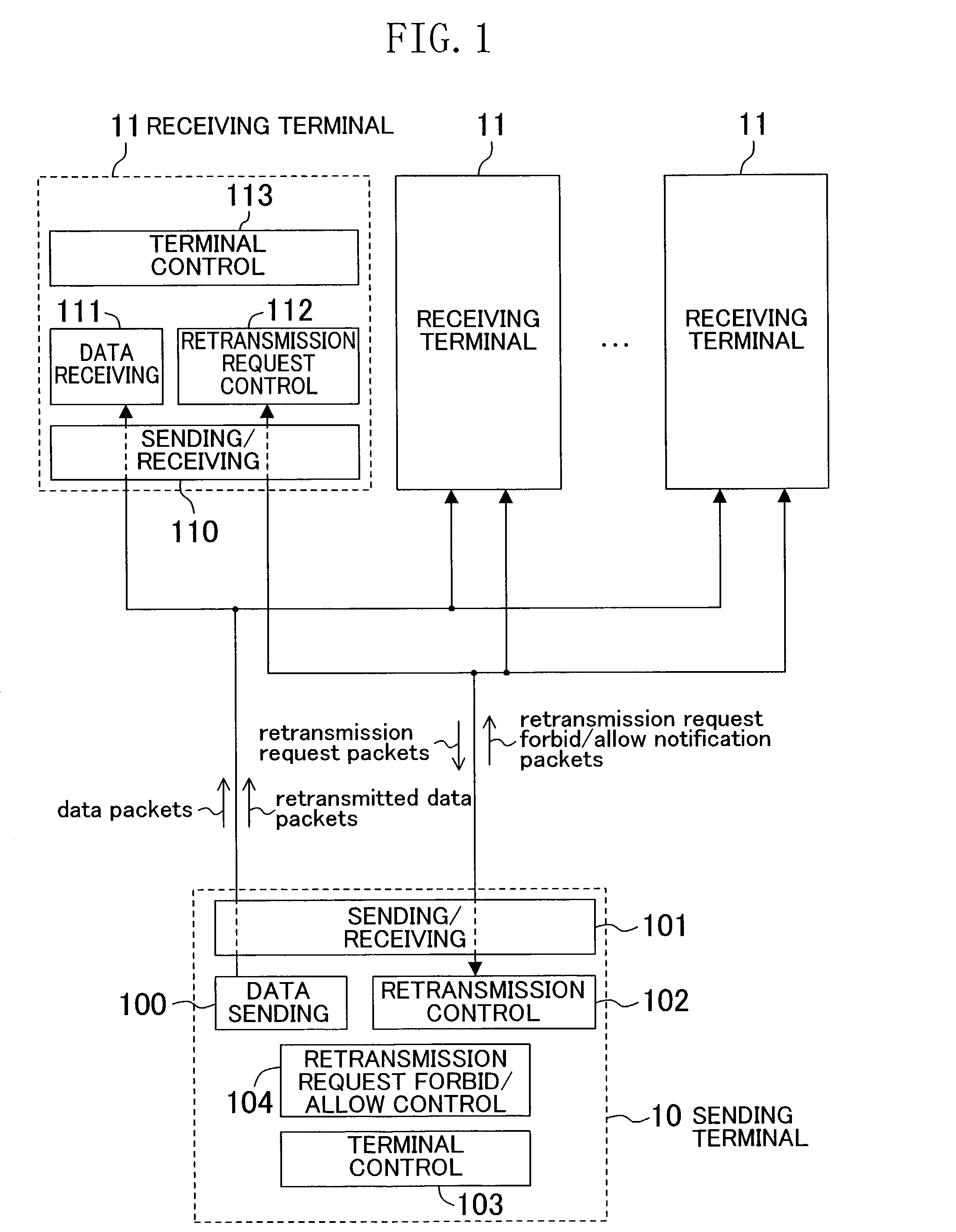
[0043]FIG. 1 is a schematic diagram illustrating an overall view of the present embodiment. In a sending terminal 10, a sending / receiving portion 101 is a means for receiving and sending packets, such as a modem or a LAN (Local Area Network). The communications environment is presumed to be an environment with packet loss generated by noise and congestion.

[0044]A data sending portion 100 is a means for taking in data from input, such as a video capture, a microphone, a file, or a shared memory, encoding the data if necessary, packetizing the data if necessary, and sending data packets to a receiving terminal 11 via the sending / receiving portion 101. It is also a means for retransmitting, upon a command from a retransmission control portion 102, the data packe...

second embodiment

[0058]The present embodiment is primarily for solving the aforementioned second problem by randomizing the retransmission requests of the receiving terminals.

[0059]FIG. 5 is a sequence diagram describing the sending / receiving method according to the present embodiment. In this example, RTP is used for the sending and receiving of data packets and RTCP is used for the sending and receiving of retransmission request packets, respectively. Observation of jumps in the sequence number of RTP packets serves as the method with which the receiving terminals 501 and 502 detect packet loss.

[0060]In FIG. 5, it is randomized whether the receiving terminals 501 and 502 send a retransmission request, and the result is that the receiving terminals 502 do not send a retransmission request packet even if packet loss occurs (503). A sending terminal 500 receiving the retransmission request packet from the receiving terminal 501 sends data packets to the receiving terminal 502 as well, even though it ...

third embodiment

[0061]The present embodiment is primarily for solving the aforementioned third and fourth problems by sending loss notification packets from the gateway.

[0062]FIG. 6 is a schematic drawing showing a overall view of the present embodiment. In FIG. 6, a sending terminal 60 is connected to a receiving terminal 61 via a gateway 62. The sending terminal 60 and the gateway 62 are connected to one another by a wired network, and the gateway 62 and the receiving terminal 61 are connected to one another by a wireless network. With this mode of connection, a case is conceivable in which the receiving terminal 61 is a mobile terminal, such as a portable telephone, connected to a server (sending terminal 60). This means, the server 60 and the gateway 62 are connected by a wired network such as an Ethernet or by ATM (Asynchronous Transfer Mode), and the receiving terminal 61 and the gateway 62 are connected by a wireless network such as a wireless LAN or by W-CDMA (Wideband Code Division Multipl...


PUM


Abstract

The packet loss in a wired section is reported to a receiving terminal (61) using a loss notification packet from a gateway (62) located at the boundary between a wired section and a wireless section, and thus the causes for packet loss are separated. Also, using this loss notification packet, the packet loss rate in the wired section and the wireless section are separately calculated and the transmission rate and robustness of the data packets are determined with a sending terminal (60) in accordance with the respective loss rate of the sections.

Description

TECHNICAL FIELD[0001]The present invention relates to a method for sending and receiving data in a network environment with innumerable receiving terminals of various specifications and capacities, such as portable telephones, portable information terminals, personal computers, and television receivers. In particular, the present invention relates to an information communications technology for efficiently transferring information when there is a mixture of information having large time series restrictions, such as audio information, and information which can be transferred even haltingly over time, such as still image data like artwork or medical images.BACKGROUND ART[0002]When packets are sent in an environment where packet loss occurs, retransmitting the lost packets enables data transmission of a high service quality. Methods providing the framework for retransmission in RTP (Realtime Transport Protocol) include sending / receiving methods for stream packets, such as W-RTP (Wirele...

Claims


Application Information

Patent Timeline
Patent Type & Authority Patents(United States)
IPC IPC(8): H04J1/16H04L12/28H04L1/00H04L1/16H04L1/18H04L1/20H04W24/08H04W28/04H04W72/04H04W72/08H04W88/16
CPCH04L1/0002H04L1/203H04L1/1838H04L1/1854H04L43/0829H04L47/10H04L47/11H04L47/14H04L47/263H04L47/40H04W28/22H04L1/1614H04L1/1809H04L2001/0097H04L2001/0098H04W28/04H04W88/16H04L65/608H04W28/02H04L65/65H04L47/25H04W8/04
Inventor ITOH, TOMOAKIYAMAGUCHI, TAKAOSATO, JUNICHIARAKAWA, HIROSHIMATSUI, YOSHINORINOTOYA, YOJI
Owner APPLE INC
Why Eureka
Try Eureka