Method for coding and decoding an information symbol

a technology of information symbols and information symbols, applied in the direction of modulated carrier systems, transmission, transmitter/receiver shaping networks, etc., can solve the problems of consecutive symbols occurring in consecutive sequences, inability to invert the transfer function of the transmission channel, etc., to reduce the isi caused, the encoder adapts to the effect of low computational cost and simple

Inactive Publication Date: 2008-02-19
NANOTRON GES FUR MIKROTECHN
View PDF7 Cites 0 Cited by
  • Summary
  • Abstract
  • Description
  • Claims
  • Application Information

AI Technical Summary

Benefits of technology

[0020]According to another advantageous embodiment, the calculating arrangement provided in the encoding device can comprise a first memory arrangement for storing the sending values already sent, a second memory arrangement for storing of channel coefficients which describe the postoscillation of the transmission channel, a multiplication arrangement for multiplying the sending values already sent with the corresponding channel coefficients, and an addition arrangement for adding up the results of the multiplication. By progressively storing the sending values already sent in the first memory arrangement and updating in time the channel coefficients in the second memory arrangement, a simple adaptation of the encoder to the given transmission situation is possible with low computational expense. The expected reception signal values can then be computed in advance in the calculating arrangement, preferably by means of the addition result, the selected channel symbol, and an expectation value taking into account the preoscillation behavior of the transmission channel. This makes it possible to factor in the preoscillation behavior of the transmission channel. In order to reduce the ISI caused by the preoscillation behavior, a prefilter adapted to the transmission channel can also be provided.

Problems solved by technology

These effects result in inter-symbol interference (ISI) between symbols occurring consecutively in time.
In the general case, it is not possible to invert the transfer function of the transmission channel and thereby eliminate the perturbing influence of the transmission channel.

Method used


Image

  • Method for coding and decoding an information symbol
  • Method for coding and decoding an information symbol
  • Method for coding and decoding an information symbol

Examples


Embodiment Construction

[0034]The preferred sample embodiment shall be explained hereafter, at first in general form and then on the special example of a BPSK modulation.

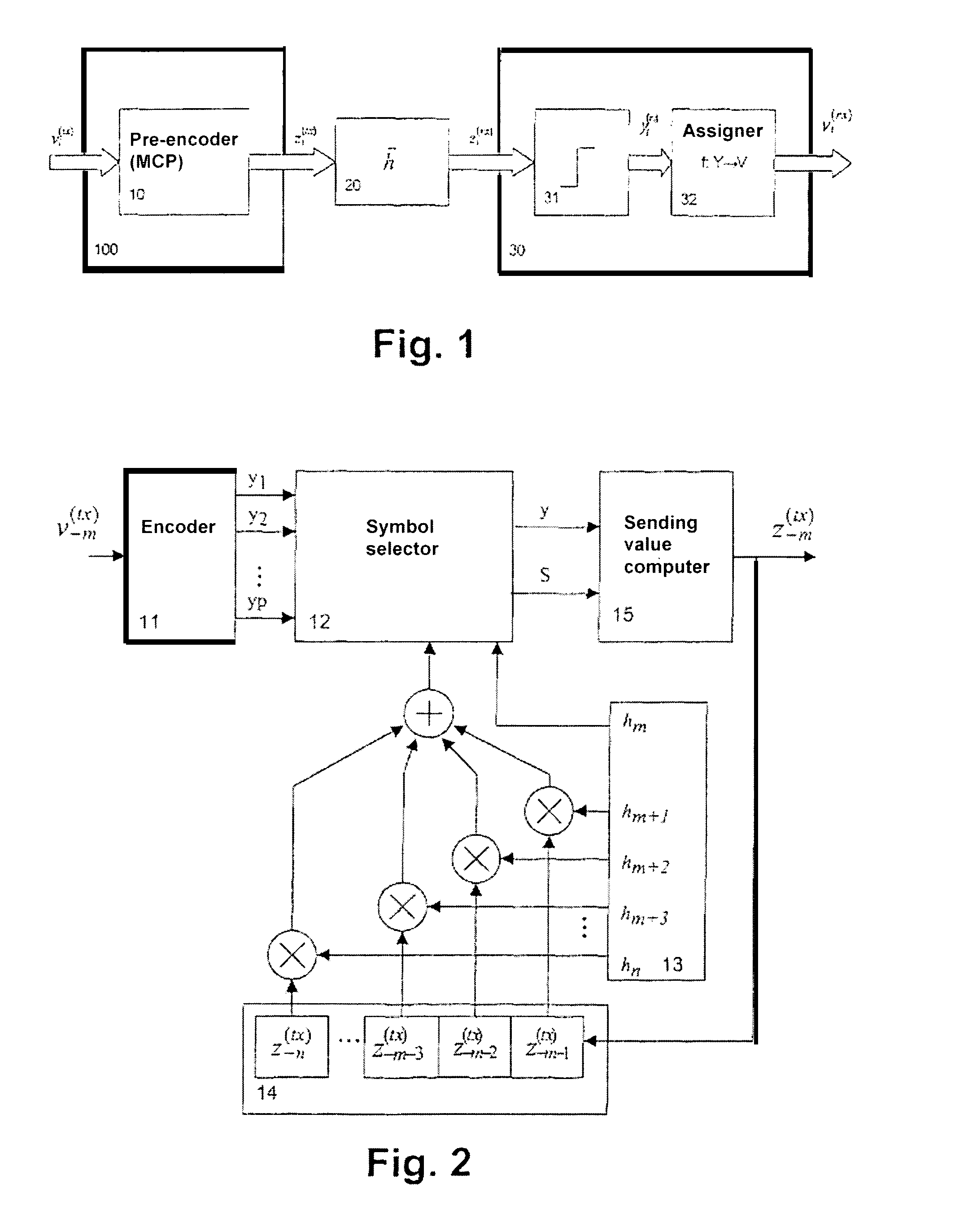
[0035]FIG. 1 shows a block diagram of the symbol flow in a baseband model during a transmission of information symbols making use of several selectable channel symbols (MCP method). According to K. D. Kammayer, “Nachrichtenüibertragung,” B. G. Teubner-Verlag Stuttgart, 2nd edition, ISBN 3-519-16142-7, complex-valued signals are designated here by block arrows. Signals, symbols and values at the transmitter side are designated with (tx), signals, symbols and values at the receiver side are designated with (rx). The index i is used as the discrete time index. For an information symbol vi(tx)εV present at the transmitter input at time i, the pre-encoder (fMCP (·)) 10 selects a channel symbol which is desirable at the receiver input and from this calculates a sending value zi(tx)εZ(tx) to be sent out. This calculation makes use of both the cha...


PUM


Abstract

A method and a device for the coding and/or decoding of an information symbol for transmission over a transmission channel or a received signal value is described and illustrated, whereby a channel symbol used for coding is selected from at least two available channel symbols by means of a pre-calculated expected received signal value. The pre-calculation is achieved, based on the echo properties of the transmission channel and transmission values already sent. A pre-coding method with low receiver-side calculation requirement is thus prepared, whereby the information symbol can be transmitted by means of various channel symbols and thus various transmission values can also be transmitted. The possible selections may be used for minimization of the transmission energy and/or to achieve a minimal disturbance or even a constructive effect through the inter-symbol interference occurring on transmission.

Description

BACKGROUND OF THE INVENTION[0001]The present invention pertains to a method for coding and decoding an information symbol or stream of information symbols to be transmitted across a transmission channel. Furthermore, the invention pertains to devices for encoding a signal to be transmitted and decoding a signal value received.[0002]Transmission channels must generally deal with echoes, multipath propagation, preoscillation and postoscillation. These effects result in inter-symbol interference (ISI) between symbols occurring consecutively in time. In the general case, it is not possible to invert the transfer function of the transmission channel and thereby eliminate the perturbing influence of the transmission channel.[0003]It is known that the perturbing influence of the transmission channel can be reduced by devices at the receiver side, such as equalizers or maximum likelihood sequence estimation.[0004]At the sending side of a transmission system, precoding represents a way of re...

Claims


Application Information

Patent Timeline
Patent Type & Authority Patents(United States)
IPC IPC(8): H04B15/00H04L25/03H04L27/18H04L27/34
CPCH04L25/03343H04L27/3405H04L25/03866H03M13/00
Inventor KOSLAR, MANFREDHACH, RAINER
Owner NANOTRON GES FUR MIKROTECHN
Why Eureka
Try Eureka