Apparatus for controlling flow rate of gases used in semiconductor device by differential pressure

a technology of differential pressure and gas flow rate, which is applied in the direction of process and machine control, liquid/fluent solid measurement, service pipe system, etc., can solve the problems of low response, large deterioration of reliability, troublesome change of compensation constant for use, etc., and achieve the effect of improving the response and reliability of the controller

Inactive Publication Date: 2008-02-26
HYUNDAI CALIBRATION & CERTIFICATION TECH CO LTD +1
View PDF8 Cites 27 Cited by
  • Summary
  • Abstract
  • Description
  • Claims
  • Application Information

AI Technical Summary

Benefits of technology

[0006]The present invention is conceived to solve the aforementioned problems in the prior art. An object of the present invention is to provide an apparatus for controlling flow rate of gases used in semiconductor device by differential pressure, wherein differential pressure is generated in the gas flowing through a flow passage and the flow rate is measured using the differential pressure of the gas, thereby greatly improving the response and reliability of the controller.
[0007]Another object of the present invention is to provide an apparatus for controlling flow rate of gases used in semiconductor device by differential pressure, wherein the flow rate of the gas can be precisely and rapidly controlled due to a fast response speed of the controller and a stable flow of the gas.
[0008]A further object of the present invention is to provide an apparatus for controlling flow rate of gases used in semiconductor device by differential pressure, wherein the controller can be manufactured and maintained conveniently and economically due to its simple structure.
[0009]A still further object of the present invention is to provide an apparatus for controlling flow rate of gases used in semiconductor device by differential pressure, wherein the degree of purity of the gas can be improved by means of a filtering function of a differential pressure generation element itself that is installed in a flow passage and generates differential pressure in a flow of the gas.

Problems solved by technology

However, the conventional heat sensitive type mass flow rate controller has a problem in that the flow rate of the gas is indirectly measured in such a manner that the temperature of the thermal resistor of the flow sensor is changed by heat capacity according to the gas flow and the temperature change in the thermal resistor is detected as the voltage change by the Wheatstone bridge, resulting in very low response.
Further, the conventional heat sensitive type mass flow rate controller has problems in that it does not ensure linearity of the relationship between the flow rate and the electromotive force of the flow sensor throughout the entire range of flow rate of the gas, and its reliability is greatly deteriorated due to changes in the sensitivity of the flow sensor according to gas pressure.
Moreover, the conventional heat sensitive type mass flow rate controller has a problem in that it is troublesome to change a compensation constant for use in the measurement of the flow rate according to the kind of gas.

Method used


Image

  • Apparatus for controlling flow rate of gases used in semiconductor device by differential pressure
  • Apparatus for controlling flow rate of gases used in semiconductor device by differential pressure
  • Apparatus for controlling flow rate of gases used in semiconductor device by differential pressure

Examples


first embodiment

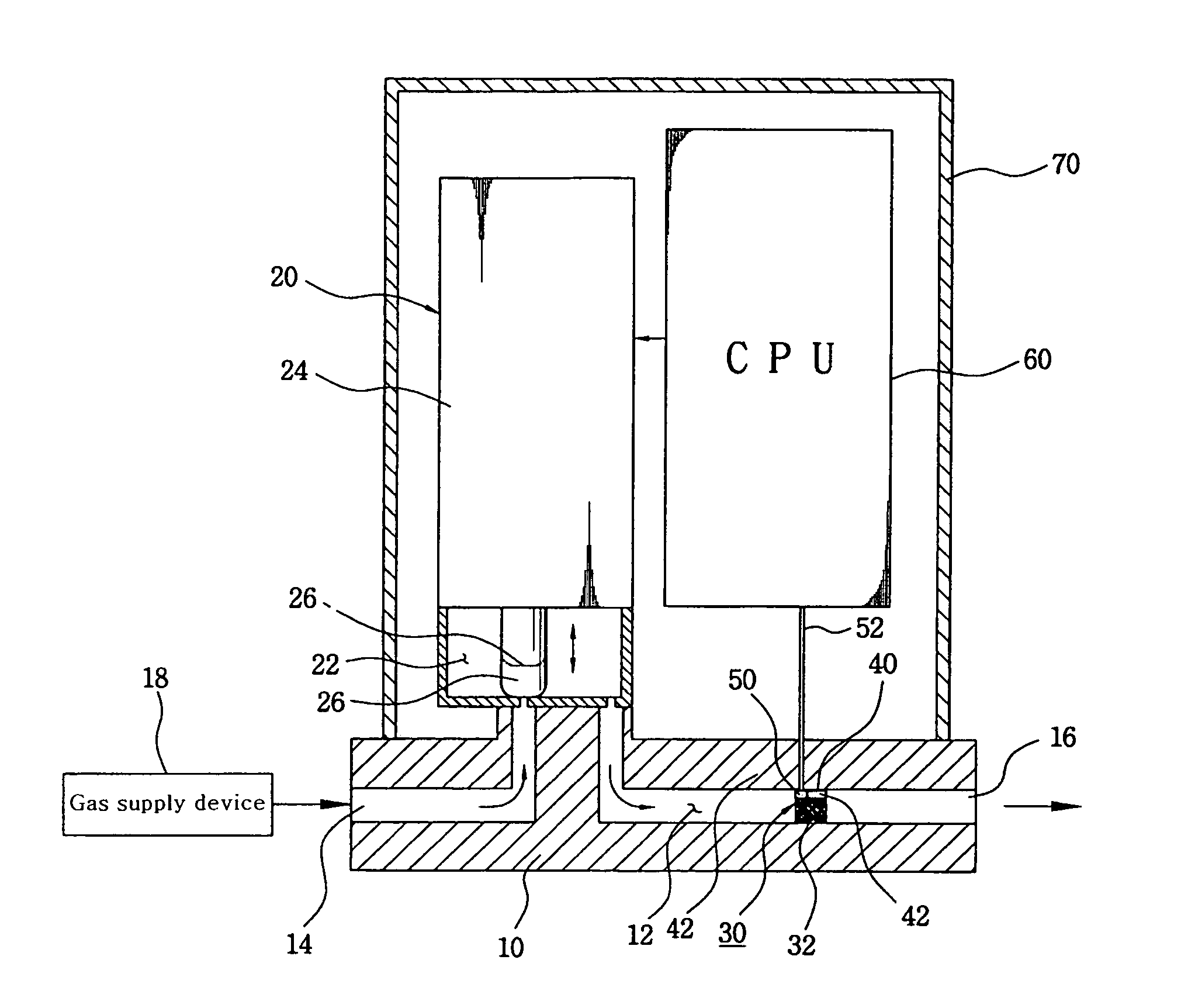
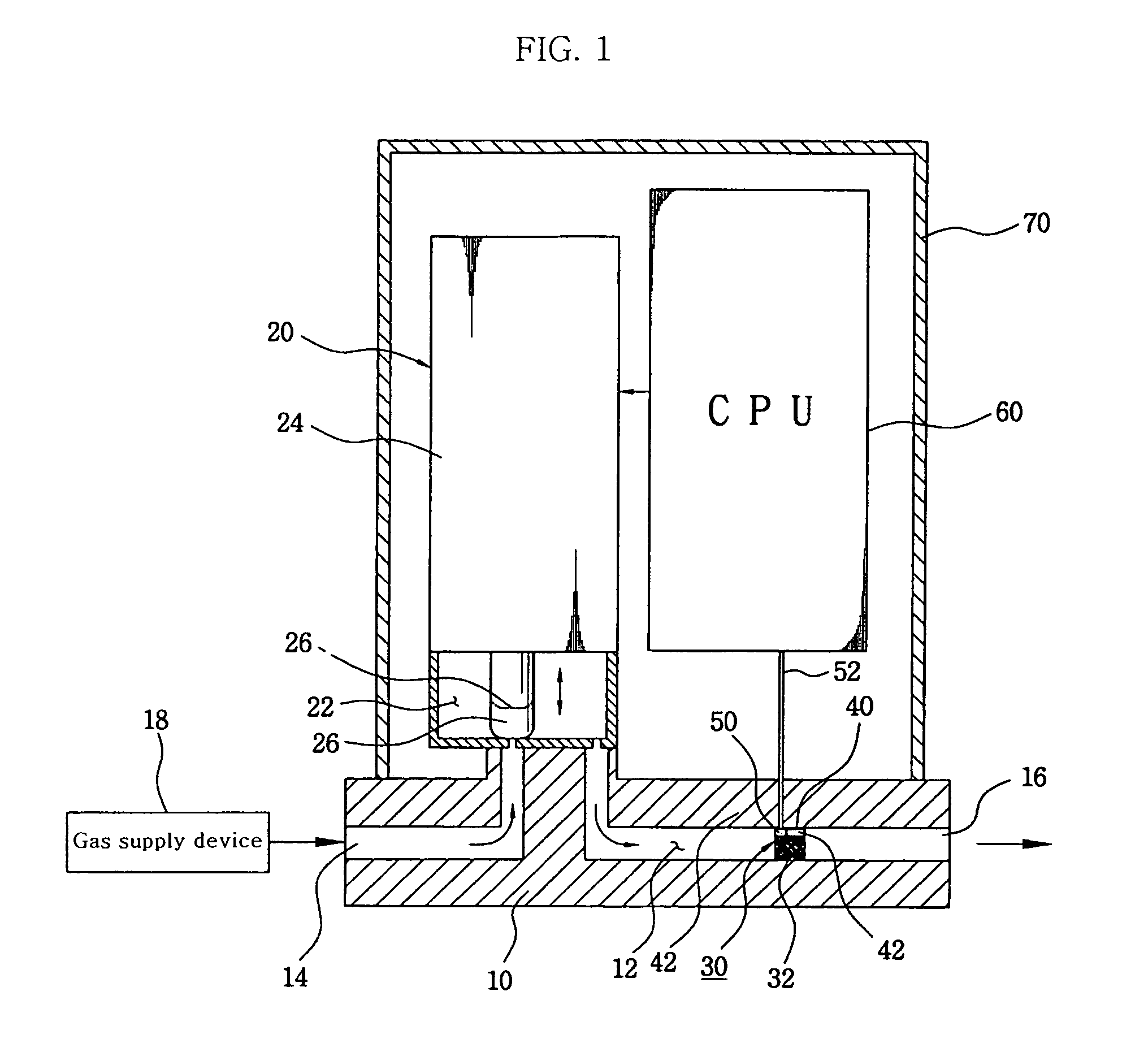
[0020]an apparatus for controlling flow rate of gases according to the present invention shown in FIGS. 1 to 3 will be first described. Referring to FIGS. 1 and 2, a body 10 defining the external appearance of the apparatus for controlling flow rate of gases according to the present invention is formed with a flow passage 12 for gases such as dopant, etchant, diffusion and purge gasses used in semiconductor device fabrication. The flow passage 12 has a gas inlet 14 and a gas outlet 16. The inlet 14 is connected to a gas supply device 18. The gas discharged through the outlet 16 is supplied to a semiconductor device fabrication process. An upstream portion of the flow passage 12 is connected to a valve chamber 22 of a control valve 20. The valve chamber 22 of the control valve 20 is provided with a valve body 26 for opening or closing the flow passage 12 by means of an operation of an actuator 24 so as to control the flow of the gas. In this embodiment, the actuator 24 of the control...

third embodiment

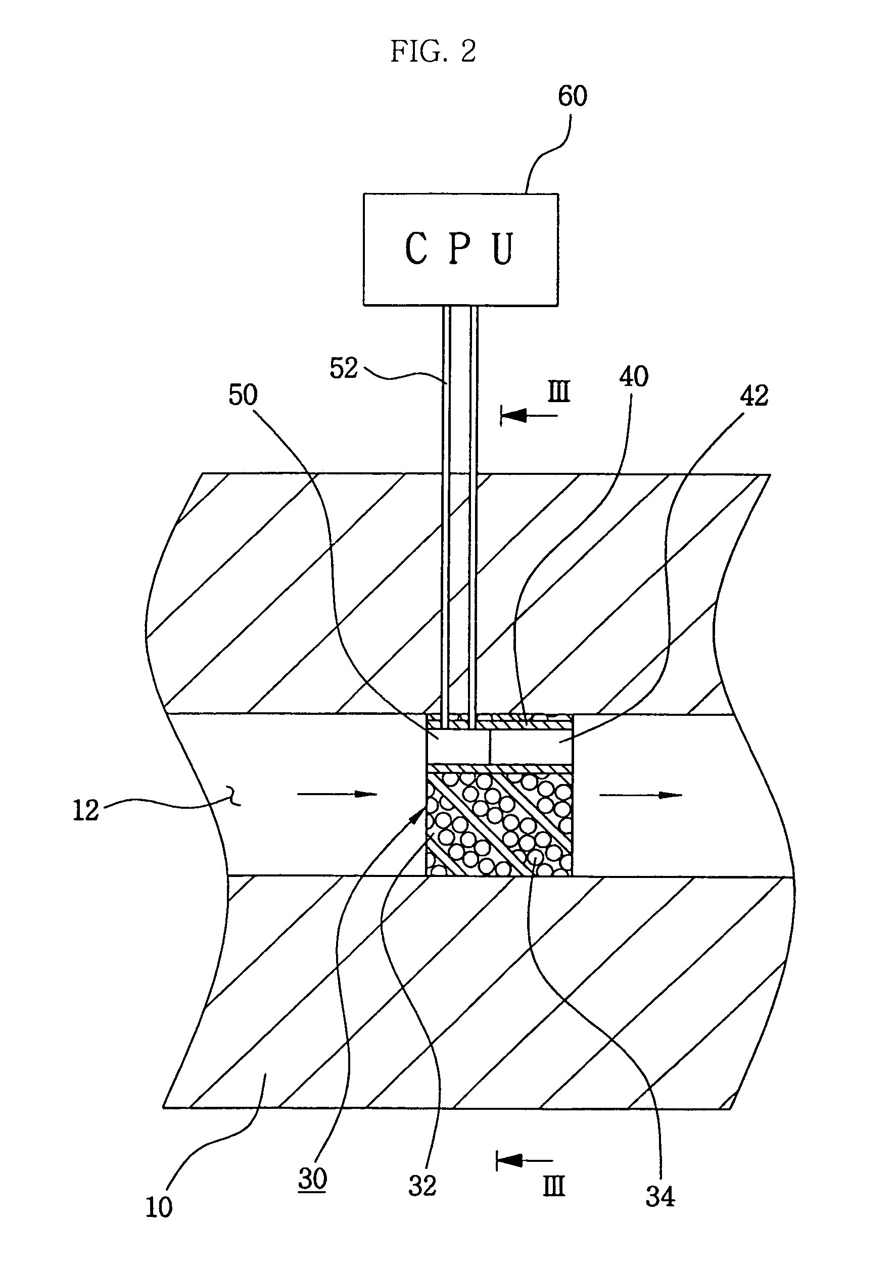
[0033]In the apparatus for controlling flow rate of gases constructed as above, the gas introduced through the inlet 14 of the body 10 flows along the flow passage 12 while passing through the respective pores 134 of the first and second vertical plate portions 136a and 136c. At this time, there is a drop in the pressure of the gas that has passed through the pores 134 having cross sectional areas narrower than that of the flow passage 12, and a pressure difference is produced between above and below the horizontal plate portion 136b. The pressure sensor 150 received in the bore 142 of the tube 140 detects the differential pressure between above and below the horizontal plate portion 136b and outputs a detection signal. The CPU 60 compares the detection signal input from the pressure sensor 150 with a set point, obtains the flow rate of the gas, and then controls the flow of the gas by opening or closing the flow passage 12 through the operation of the actuator 24 of the control va...


PUM

PropertyMeasurementUnit
flow rateaaaaaaaaaa
differential pressureaaaaaaaaaa
pressureaaaaaaaaaa

Abstract

Provided is apparatus for controlling flow rate of gases used in semiconductor device by differential pressure by generating differential pressure in a fluid path. A differential pressure generation element generates pressure difference in the fluid path of gases used in semiconductor device fabrication, a pressure, sensor which is installed at a bypass of the fluid path detects the pressure difference, and a central processing unit (CPU) measures and controls a flow rate of the gases, thereby the present invention is capable of controlling the flow rate precisely and rapidly, and enhancing the degree of purity of the gases by the filtering function of the differential pressure generation element itself.

Description

RELATED APPLICATIONS[0001]The present application is based on International Application Number PCT / KR04 / 001533, filed Jun. 24, 2004, and claims priority from, Korean Application Number 10-2003-0042584, filed Jun. 27, 2003, the disclosure of which is hereby incorporated by reference herein in its entirety.TECHNICAL FIELD[0002]The present invention relates to an apparatus for controlling flow rate of gases used in semiconductor device fabrication by differential pressure, and more particularly, to an apparatus for controlling flow rate of gases used in semiconductor device fabrication by generating differential pressure in a flow passage through which the gas flows.BACKGROUND ART[0003]As well known, semiconductor device fabrication employs gases such as dopant gas, etchant gas, diffusion gas and purge gas used for manufacturing semiconductor devices. The semiconductor device fabrication requires that such gases have high purity. Further, the flow rates of the gases that determine char...

Claims


Application Information

Patent Timeline
Patent Type & Authority Patents(United States)
IPC IPC(8): G05D7/06H01L21/02
CPCG05D7/0635Y10T137/8326Y10T137/7761Y10T137/7722Y10T137/7759H01L21/02
Inventor AHN, KANG-HO
Owner HYUNDAI CALIBRATION & CERTIFICATION TECH CO LTD
Why Eureka
Try Eureka