Turbine shroud assembly with enhanced blade containment capabilities

Active Publication Date: 2008-02-26
HEICO CORP
View PDF6 Cites 38 Cited by
  • Summary
  • Abstract
  • Description
  • Claims
  • Application Information

AI Technical Summary

Benefits of technology

[0015]FIG. 2 is an enlarged, partial sectional view of one embodiment of the inventive turbine shroud h

Problems solved by technology

These ejection events have the potential for hazarding the aircraft.
Increasing the casing thickness is expensive, as entire casings must be replaced if a current engine is to be retrofitted with a casing of enhanced thickness.
This extra piece of sheet metal is commonly referred to as a “doubler.” However, the '242 and '026 patents disclose drawbacks to the “doubler” design because the brazing interface is relatively brittle and

Method used


Image

  • Turbine shroud assembly with enhanced blade containment capabilities
  • Turbine shroud assembly with enhanced blade containment capabilities
  • Turbine shroud assembly with enhanced blade containment capabilities

Examples


Example

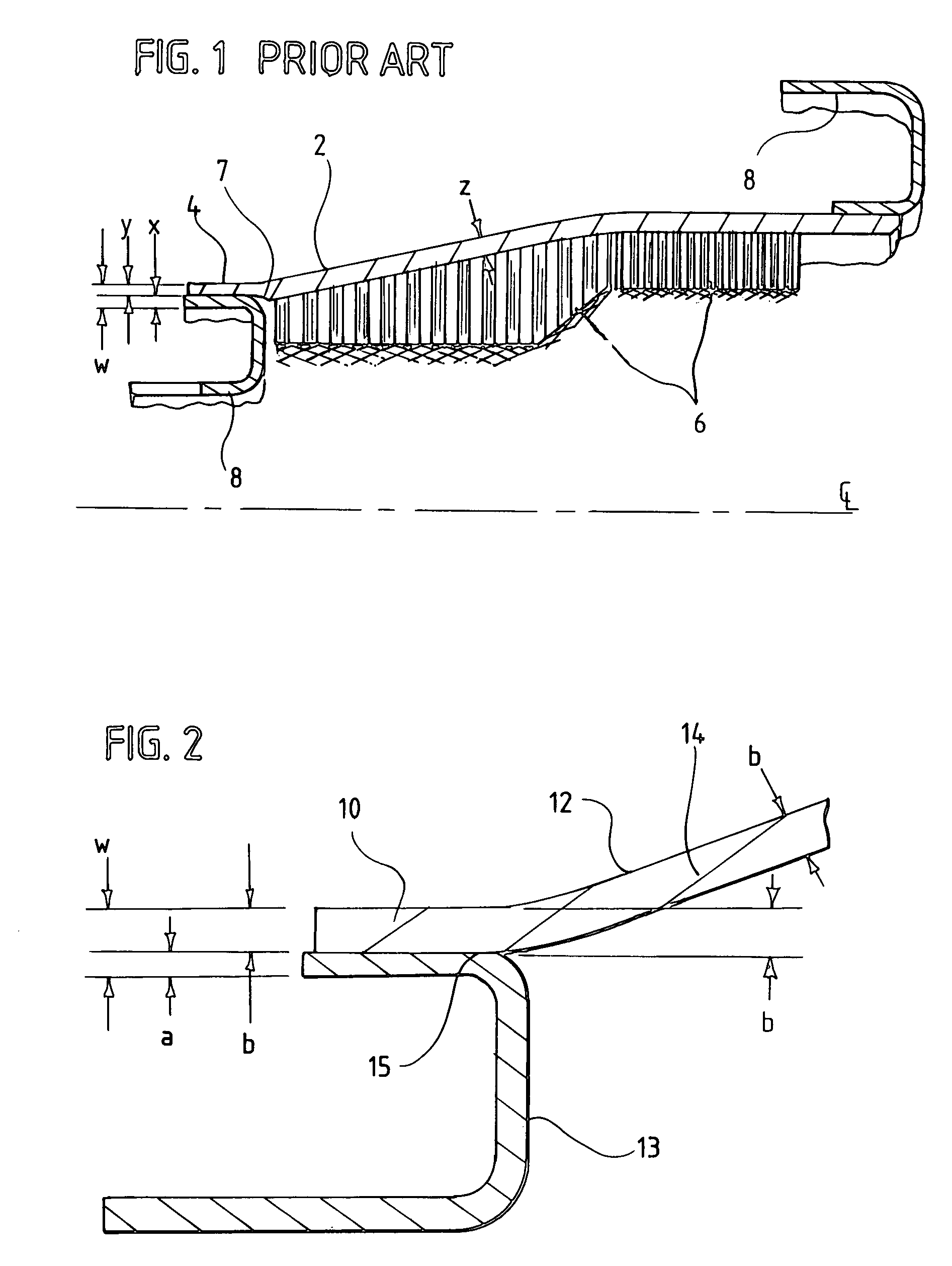
[0022]FIG. 1 is an example of a design referred to in the '242 and '026 patents. Referring now to FIG. 1 it can be seen that the blade containment shield portion 2 of the backsheet is of thickness ‘z’, while the rail portion 4 is of conventional thickness ‘y’, which is less than ‘z’. The mounting hook 8 is of conventional thickness ‘x’. The combined thickness of the rail 4 and the mounting hook 8 is ‘w’. Rub strip 6 also is shown. Interface 7 between the thicker middle section 2 and thinner rails 4 is a potential weak link in the backsheet, where failure is likely to occur in the event of a turbine blade ejection event.

[0023]In one embodiment the present invention eliminates the weak link interface between the thickened blade containment shield and the thinner rails. Referring now to FIG. 2, it can be seen that this inventive backsheet design is a single piece backsheet 12 of uniform thickness ‘b’, such that the mounting rails 10 and the blade containment shield 14 have the same thi...


PUM


Abstract

A low pressure turbine shroud assembly includes a backsheet with enhanced blade containment capabilities that is sized to be retrofitted into a conventional low pressure turbine assembly. The backsheet has first and second mounting rails at axially opposite ends thereof and a blade containment sheet shield disposed therebetween. The rails and the containment shield are of a uniformly increased thickness as compared with a conventional backsheet rail and containment shield design. The assembly also includes a modified mounting hook for mounting the improved backsheet to a case extending around the shroud. The mounting hook is of reduced thickness as compared with a conventional mounting hook for a conventional backsheet proportional to the increase in thickness of the backsheet. The assembly also can include a rub strip disposed between a radially inner surface of the backsheet and a turbine blade.

Description

CROSS REFERENCE TO RELATED APPLICATIONS[0001]This application claims the benefit of priority from and incorporates the disclosures of Provisional Application Ser. No. 60 / 532,543, entitled Alternate Blade Containing Turbine Shroud, and filed on Dec. 24, 2003; Provisional Application Ser. No. 60 / 541,801, entitled Laminated Containment System (LCS) For Blade Containing Turbine Shroud, and filed on Feb. 4, 2004 and Provisional Application Ser. No. 60 / 585,613, entitled Alternate Blade Containing Turbine Shroud, and filed on Jul. 6, 2004.BACKGROUND OF THE INVENTION[0002]This invention relates to jet engine low-pressure turbine assemblies, and more particularly to an improved system for containing ejected turbine blades and other failure events.[0003]An area of recent concern in aircraft engine applications is the containment of low-pressure turbine (“LPT”) blades. Over the past several years incidents have occurred where LPT blades have been liberated from the respective disks and have es...

Claims


Application Information

Patent Timeline
IPC IPC(8): F01D11/08
CPCF01D11/127F01D21/045F01D25/246Y02T50/671Y02T50/60
Inventor STINE, FREDERICK J.TUCKER, JAMES W.SZPUNAR, STEPHEN J.
Owner HEICO CORP
Why Eureka
Try Eureka