Lighter with flint igniter

a technology of flint igniter and lighter, which is applied in the field of lighters, can solve the problems of no effective spark generation, high manufacturing cost, and no electric igniter, and achieve the effect of prolonging the life of the lighter

Inactive Publication Date: 2008-02-26
WONG CHI LAM +1
View PDF23 Cites 6 Cited by
  • Summary
  • Abstract
  • Description
  • Claims
  • Application Information

AI Technical Summary

Benefits of technology

[0009]One of the main objectives of this invention is to provide a lighter with a flint igniter composed of the flint ignition structure and candle flame outlet, wherein said flint igniter structure produces sparks lighting up fuel gas from the candle flame outlet and turns it into a flame which in turn ignites fuel gas from the candle flame outlet and turns it into a flame which in turn ignites fuel gas in the combustion chamber of the assembly so as to make a strong windproof torch with high temperature. And as the sparking end of the flint of said flint igniter structure is lower than the outlet of the combustion chamber of the support frame, the block of the diverting nozzles or quick flow nozzles by the powder generated by the flint when making sparks is effectively prevented and the life of use of the lighter is prolonged.
[0013]Another objective of this invention is to provide the lighter with a flint igniter wherein a separation structure is provided between the gas mixing chamber of the assembly and the candle flame outlet, so as to better prevent flint powder from falling into the gas mixing chamber.
[0014]Another objective of this invention is to provide the lighter with a flint igniter wherein the support frame of the lighter' housing and the combustion chamber are structured separately, so as to reduce conduction of the high temperature of the combustion chamber to the lighter's body.
[0015]Another objective of this invention is to provide the lighter with a flint igniter wherein the original design of the ordinary lighter is not significantly changed so that the manufacturing cost thereof is maintained low.

Problems solved by technology

However, it had been known that such an electronic igniter has a few defects: 1) The times an electronic ignition is extremely limited—no effective spark could be produced after 2,000-3,000 times of ignition.
For a few of such lighters, their times may come up to above 5,000, but their manufacturing costs are high and once used over, they must be discarded; 2) The combustion chamber may be ignited only if the sparking point of the electronic ignition means be separated from the diverting nozzle for a certain distance and a height, or the rate of ignition success would be low or even the lighter fails to ignite.
Because of such delicate requests for the separated distance and height result, the passing rate in the process of assembling the products is low, making the manufacturing cost raised; 3) The electronic igniter must have conductor wires which are covered with rubber or plastics for insulation, and the combustion chamber however has a high temperature which may take part of the conductor wires covered with rubber or plastic in the combustion chamber melted when the lighter being lighted up for a bit longer time, and further leads to deviated sparking and even failure of ignition.
4) The rubber or plastic cover of the conductor wires may be cut or pulled open during assembly process, which may result in electric leakage.
However, as the flame generated with such structure is weak, it is difficult to light up an article in open air, and it is particularly true when it is used to light up hard or thick tobacco.

Method used


Image

  • Lighter with flint igniter
  • Lighter with flint igniter
  • Lighter with flint igniter

Examples


Embodiment Construction

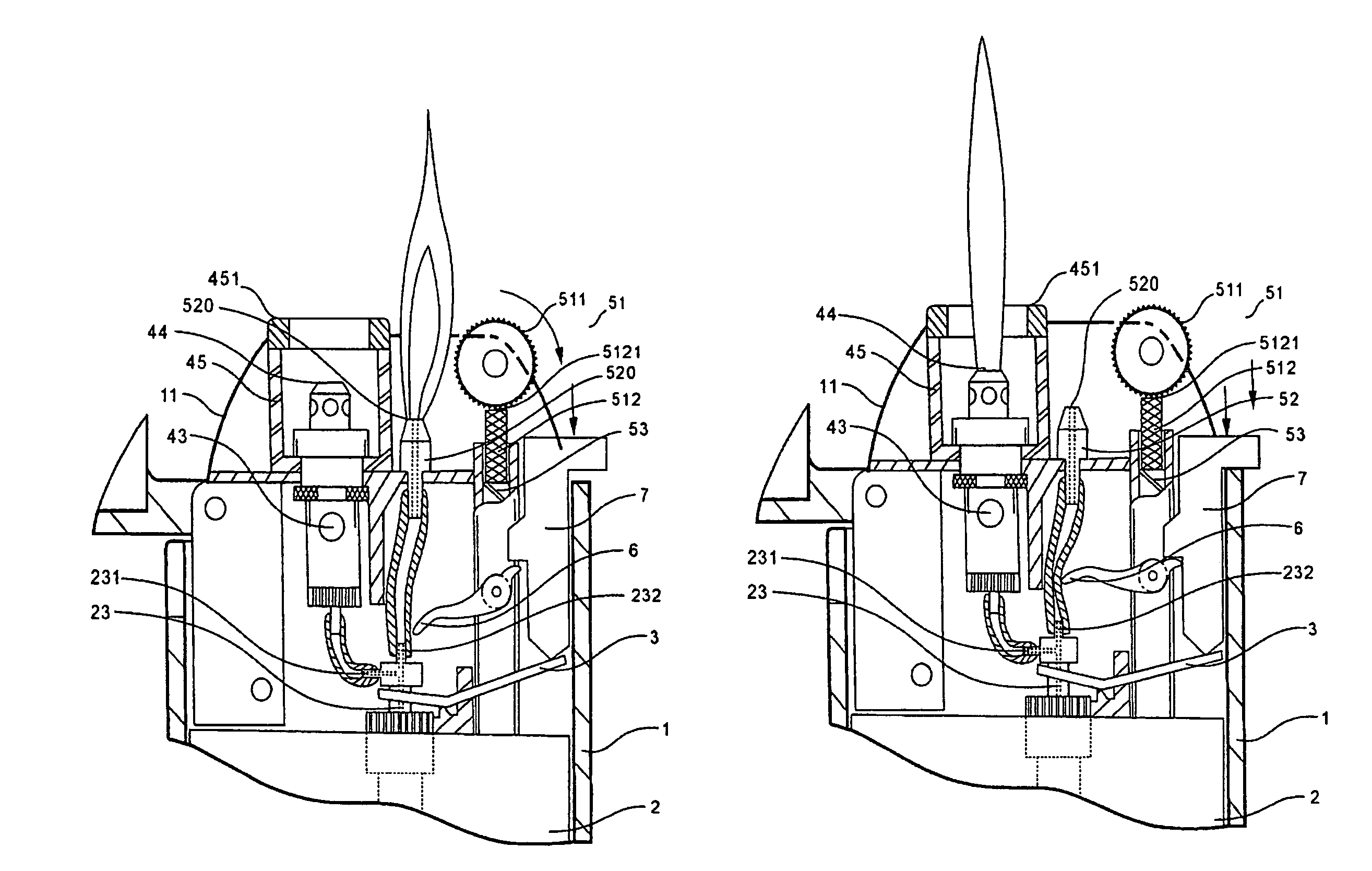
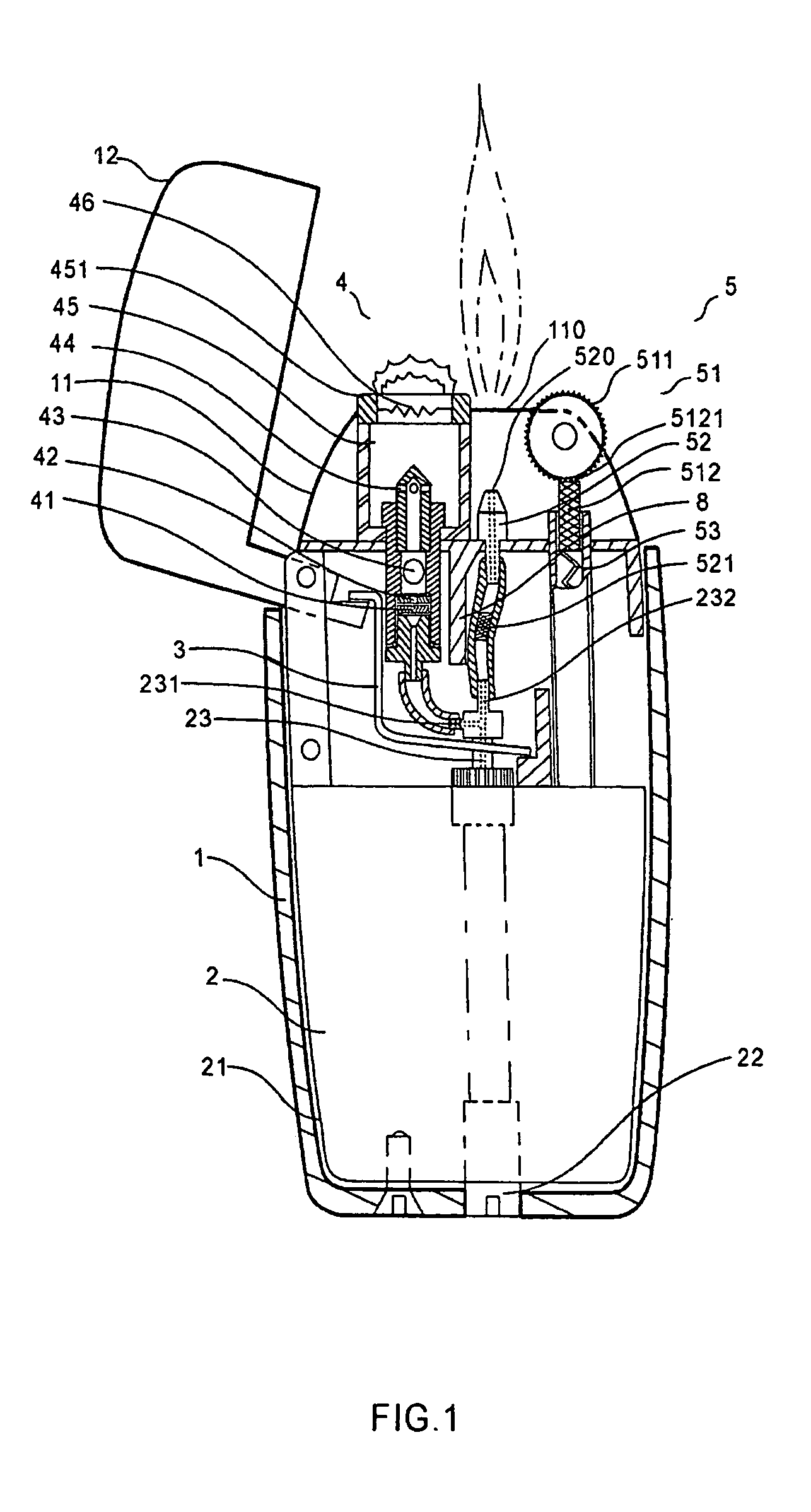
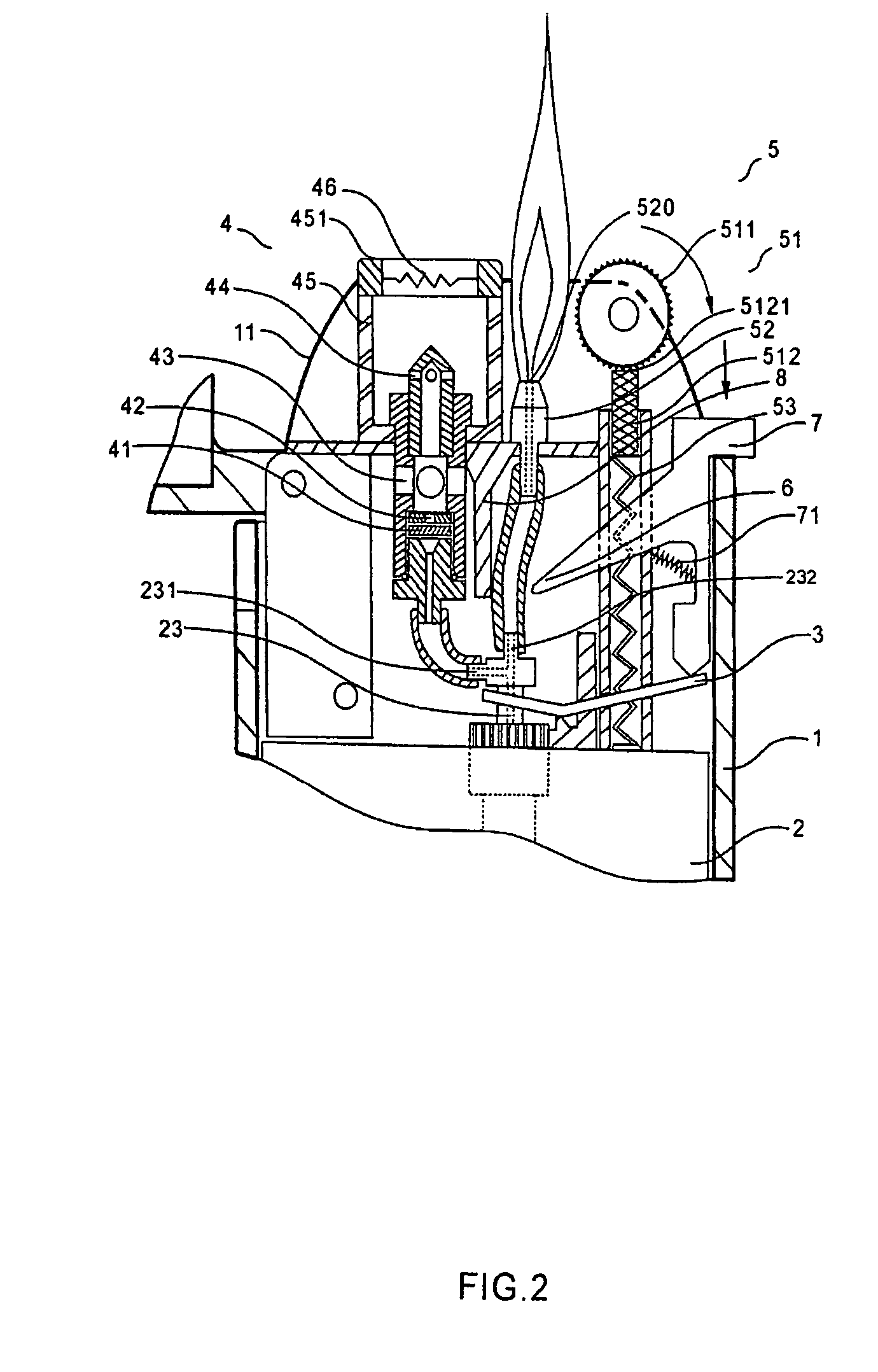
[0033]Referring to FIG. 1. The preferred embodiment of the lighter with flint igniter according to the present invention includes: a housing 1 with support frame 11, a gas container 2 with outlet valve 23, and an inlet valve 22 (that may be included) for replenishing liquid fuel, an outlet control lever 3 for acting on outlet valve 23 of gas container 2, an assembly 4 connected with the gas diverting passage 231 of the outlet valve 23 and composed of a filter 41, a quick flow nozzle 42, a gas mixing chamber 43, a diverting nozzle 44 and a combustion chamber 45, igniter 5 for lighting up the gas from the combustion chamber 45, igniter 5 for lighting up the gas from the combustion chamber 45, a metal wire 46 that may be installed on the top of combustion chamber 45. Said igniter 5 includes a flint ignition structure 51 at the side of combustion chamber 45 and candle flame outlet 52 provided between the combustion chamber 45 and flint ignition structure 51. A second gas diverting pass ...


PUM


Abstract

A lighter includes a flint igniter igniting a flame positioned adjacent to a torch nozzle thereof to light up gas emitted from the torch nozzle to form a torch in which the gas released from a gas container of the lighter is distributed to have portion emitted from a flame outlet for producing the flame while the other portion is emitted from the torch nozzle and ignited by the flame produced at the flame outlet. After lighting up the gas to form the torch, the gas from the flame outlet is blocked to stop the ignition flame.

Description

CROSS REFERENCE OF RELATED APPLICATION[0001]This is a divisional application of a non-provisional application, application Ser. No. 10 / 298,392, filed Nov. 18, 2002 now abandoned, in which the benefit of domestic priority date is claimed.BACKGROUND OF THE PRESENT INVENTION[0002]1. Field of Invention[0003]The present invention relates to a lighter and, in particular, to a sort of lighter having a flint igniter and using inflammable gas as fuel stored in liquidness.[0004]2. Description of Related Arts[0005]Currently, lighters using inflammable gas stored in liquidness (such as butane) as fuel usually consist of the following components: a) a housing, b) a fuel container with gas outlet valve, c) a gas outlet control lever for acting on the outlet valve of the fuel container, d) an assembly connected to said outlet valve composed of a nozzle, a gas mixing chamber, a diverting nozzle and a combustion chamber, e) an electronic igniter with ignition wires.[0006]As for lighters, they are ad...

Claims


Application Information

Patent Timeline
Patent Type & Authority Patents(United States)
IPC IPC(8): F23Q2/16F23Q2/173F23Q2/46F23Q2/48
CPCF23Q2/162F23Q2/48
Inventor WONG, CHI LAMWANG, LIAN
Owner WONG CHI LAM
Why Eureka
Try Eureka