High-speed vitreous cutting system

a cutting system and high-speed technology, applied in the field of devices, can solve the problems of high cutting rate, hazardous removal of vitreous close to the retina, and limited pneumatic pressure at the handpiece end of the tubing,

Inactive Publication Date: 2008-02-26
MEDICAL INSTR DEVMENT LAB
View PDF40 Cites 49 Cited by
  • Summary
  • Abstract
  • Description
  • Claims
  • Application Information

AI Technical Summary

Problems solved by technology

This, in turn, can make removal of vitreous close to the retina hazardous, as the retina may become detached or may be inadvertently drawn into the cutting port.
The rate at which the pneumatic pressure at the handpiece end of the tubing can change is limited by the physics of compressible-gas flow.
While a high cutting rate is desirable for removing vitreous close to the retina, a high cutting rate is not desirable for removing material at other locations in the eye.
Despite the known benefits of having an adjustable-speed, pneumatic cutter that is also capable of operating at high speeds, few if any cutters exist that offer such functionality.
Since high-speed choices are limited, some surgeons have resorted to using modern electrically driven probes even though they are expensive, heavy, and have a tendency to vibrate excessively.

Method used


Image

  • High-speed vitreous cutting system
  • High-speed vitreous cutting system
  • High-speed vitreous cutting system

Examples


Embodiment Construction

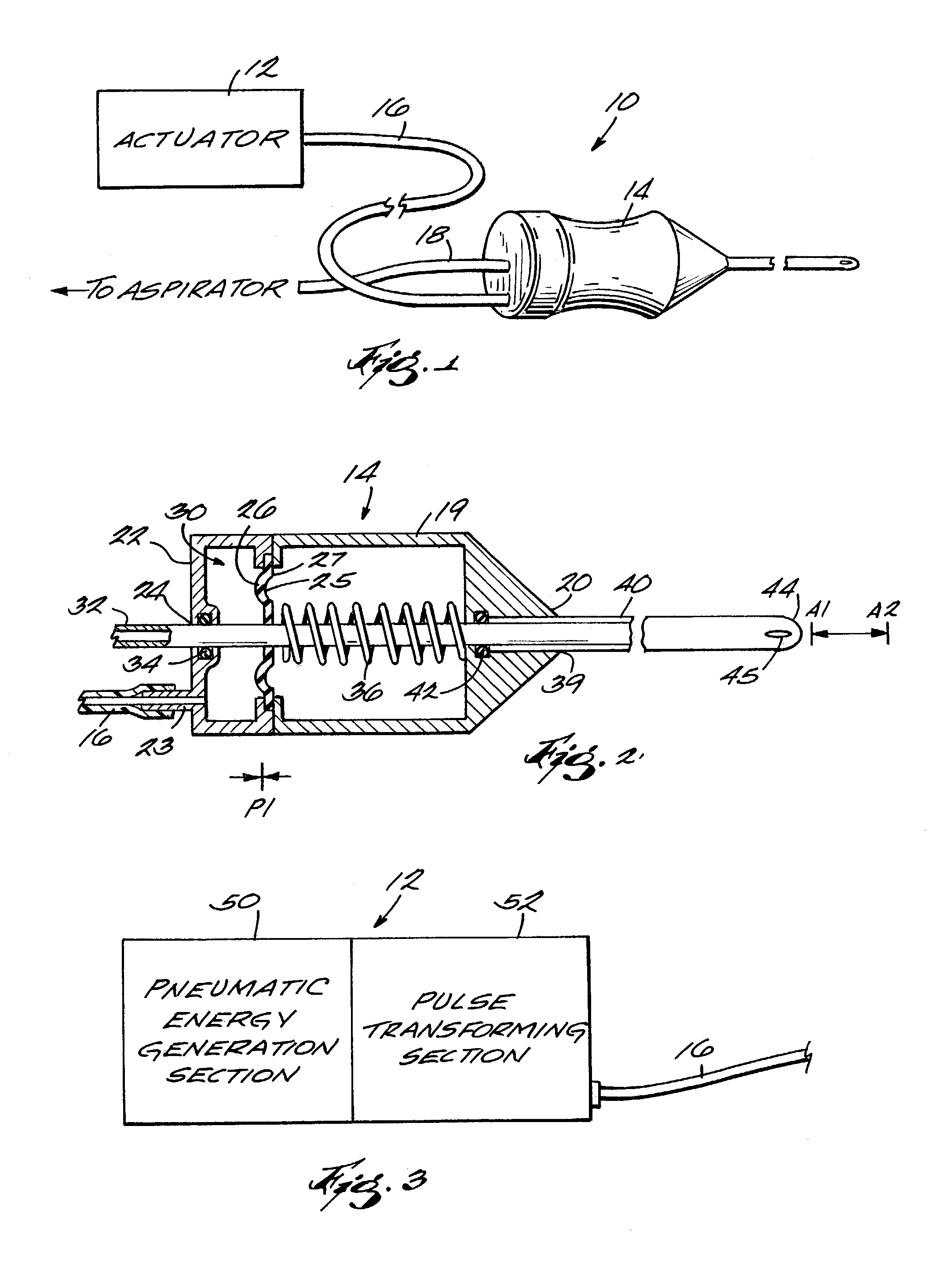
[0039]A generic high-speed vitreous cutting system 10 is shown FIG. 1. The system 10 includes an actuator 12 and a cutter 14 connected to the actuator through a tubing 16. The cutter is also connected through a tubing 18 to an aspiration system, which is separate from the vitreous cutting system 10. Preferably, the tubings 16 and 18 are joined as a single, twin-bore tubing. Typically, the tubing is 72″ to 84″ in length.

[0040]As best seen by reference to FIG. 2, the cutter 14 is a pneumatically driven, axial guillotine-type vitreous probe or cutter. The cutter has a generally cylindrically-shaped housing 19 designed to be held in a human hand and may be approximately 1.5″ in length. The housing 19 has a front end 20 and a rear end 22. The rear end 22 has a connector 23, designed to receive one end of the tubing 16, and a center opening 24. Inside the housing 19 is a flexible diaphragm / piston 25 having a first side 26 and a second side 27. The first side 26 and rear end 22 define a re...


PUM


Abstract

A high-speed pneumatic cutting system having a cutter and an actuator. The cutter is a guillotine-type, pneumatic cutter that receives a train of pressure pulses from the actuator. The actuator is designed to capture pressure pulses it receives from a pneumatic energy source in a surgical machine, such as a vitrectomy machine, or to generate its own pneumatic energy. The actuator has an accumulator coupled to the outlet of the pneumatic energy and a pressure transducer that senses the pressure level inside the accumulator. A control and display unit with a plurality of input mechanisms receives inputs from a user who selects a desired cutting rate or frequency for the cutter. The control and display unit produces an output signal based on the inputs received. The outputs from the control and display unit and the pressure transducer are sent to a waveform shaping circuit. The waveform shaping circuit produces a command signal based on the inputs that it receives. The command signal is delivered to a valve that is coupled in fluid communication to the accumulator. The valve is opened and closed according to the command signal to produce a pulse train that will operate the cutter at the selected cutting rate. The actuator may be designed as a stand-alone unit or may be integrated into a surgical machine.

Description

RELATED APPLICATIONS[0001]This application is a divisional of U.S. patent application Ser. No. 09 / 693,107, filed Oct. 20, 2000, now U.S. Pat. No. 6,575,990 which claims the benefit of U.S. Provisional Application No. 60 / 160,727 filed Oct. 21, 1999.FIELD OF INVENTION[0002]The present invention relates to devices for performing micro-surgical procedures in the posterior portion of the eye. More particularly, the present invention relates to a high-speed pneumatically driven vitreous cutter.BACKGROUND OF THE INVENTION[0003]The instrument most commonly used, and generally preferred, for vitreous surgery is a pneumatically-operated axial guillotine cutter. A typical pneumatically-operated guillotine cutter has a handpiece that includes a needle with a cutting / aspiration port located near the needle's distal end. The handpiece receives pneumatic power from a vitreoretinal surgical system (or console). Often, the system also provides aspiration and illumination functions.[0004]Although num...

Claims


Application Information

Patent Timeline
Patent Type & Authority Patents(United States)
IPC IPC(8): A61B17/32A61B17/00A61F9/007
CPCA61B17/32002A61B2017/00159A61B2017/00172A61B2017/00181A61B2017/0019A61B2017/00544A61F9/00763
Inventor WANG, CARL C.PETERSON, ERIK W.
Owner MEDICAL INSTR DEVMENT LAB
Why Eureka
Try Eureka