
Waveform shapes for treating neurological disorders optimized for energy efficiency

a neurodegenerative disorder and waveform technology, applied in the field of system and method of stimulating nerves, can solve the problems of sacrificing clinical efficacy, generating unwanted side effects, and reducing the volume of implantable stimulators, so as to prolong the battery life of stimulators, reduce the cost and risk of battery replacement surgery, and optimize the energy-efficiency of stimulation waveforms.

Active Publication Date: 2012-05-31
NDI MEDICAL
View PDF16 Cites 42 Cited by
  • Summary
  • Abstract
  • Description
  • Claims
  • Application Information

AI Technical Summary

Benefits of technology

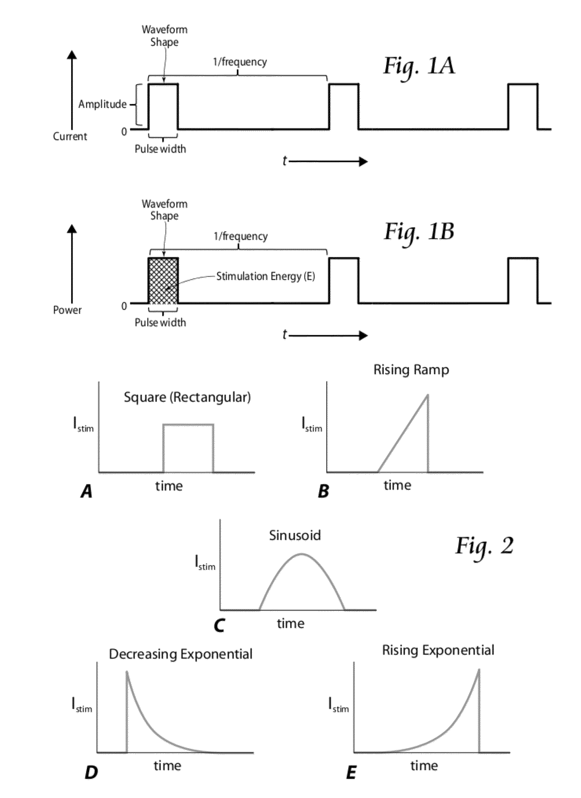
[0011]One aspect of the invention provides systems and methodologies that couple a genetic algorithm (GA) to a computational model of extracellular stimulation of a mammalian myelinated axon, to derive a set of stimulus waveforms that are optimized for energy efficiency. This aspect of the invention makes it possible in a systematic way to generate and analytically validate energy-optimal waveform shapes.
[0013]The optimized energy-efficiency of the stimulation waveforms derived according to the invention make it possible to prolong battery life of stimulators, thus reducing the frequency of recharge intervals, the costs and risks of battery-replacement surgeries, and the volume of implantable stimulators.

Problems solved by technology

When the energy of a primary cell battery is depleted, the entire stimulator must be replaced through an expensive and invasive surgical procedure.
The problem is how one alters stimulation parameters to achieve this objective without sacrificing clinical efficacy and generating unwanted side effects.
The charge delivered during a stimulus pulse contributes to the risk of tissue damage (Yuen et al.
If energy-efficient stimulation parameters deliver excessive amounts of charge, then the benefits of high energy efficiency are diminished.
However, in more realistic models and in vivo experiments, the inventors have found that the rising exponential waveform proved to be no more energy-efficient than rectangular, ramp, or decaying exponential waveforms.
In fact, in realistic membrane models, the inventors have found that energy-optimal waveform shapes cannot be determined analytically because of the complexity and non-linearity of the equations that define the excitable membrane in the model.
Also, a “brute force” method of testing every possible waveform shape is not feasible since the number of possible waveform shapes is infinite.

Method used


Image

  • Waveform shapes for treating neurological disorders optimized for energy efficiency
  • Waveform shapes for treating neurological disorders optimized for energy efficiency
  • Waveform shapes for treating neurological disorders optimized for energy efficiency

Examples


Embodiment Construction

I. System Overview

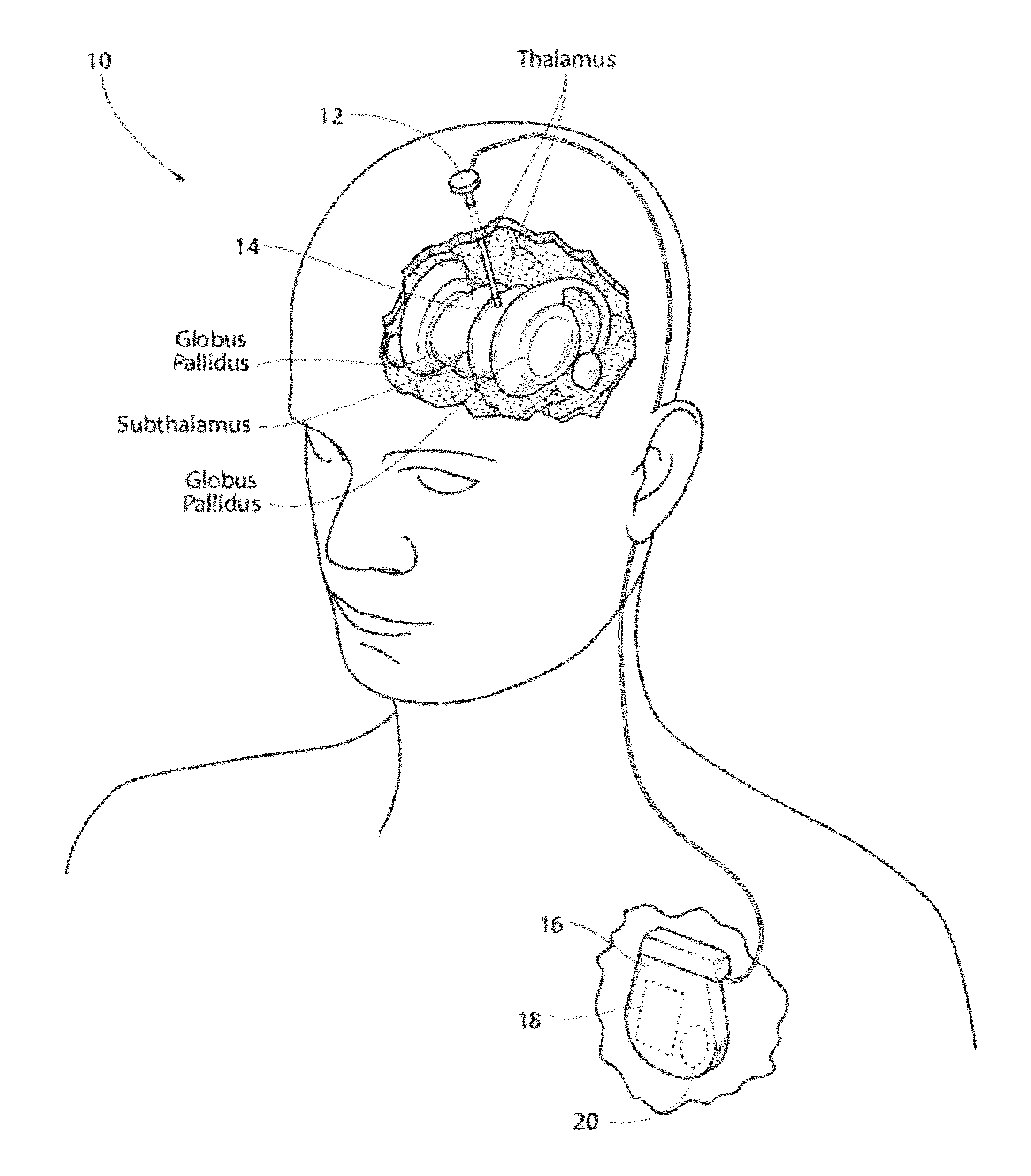
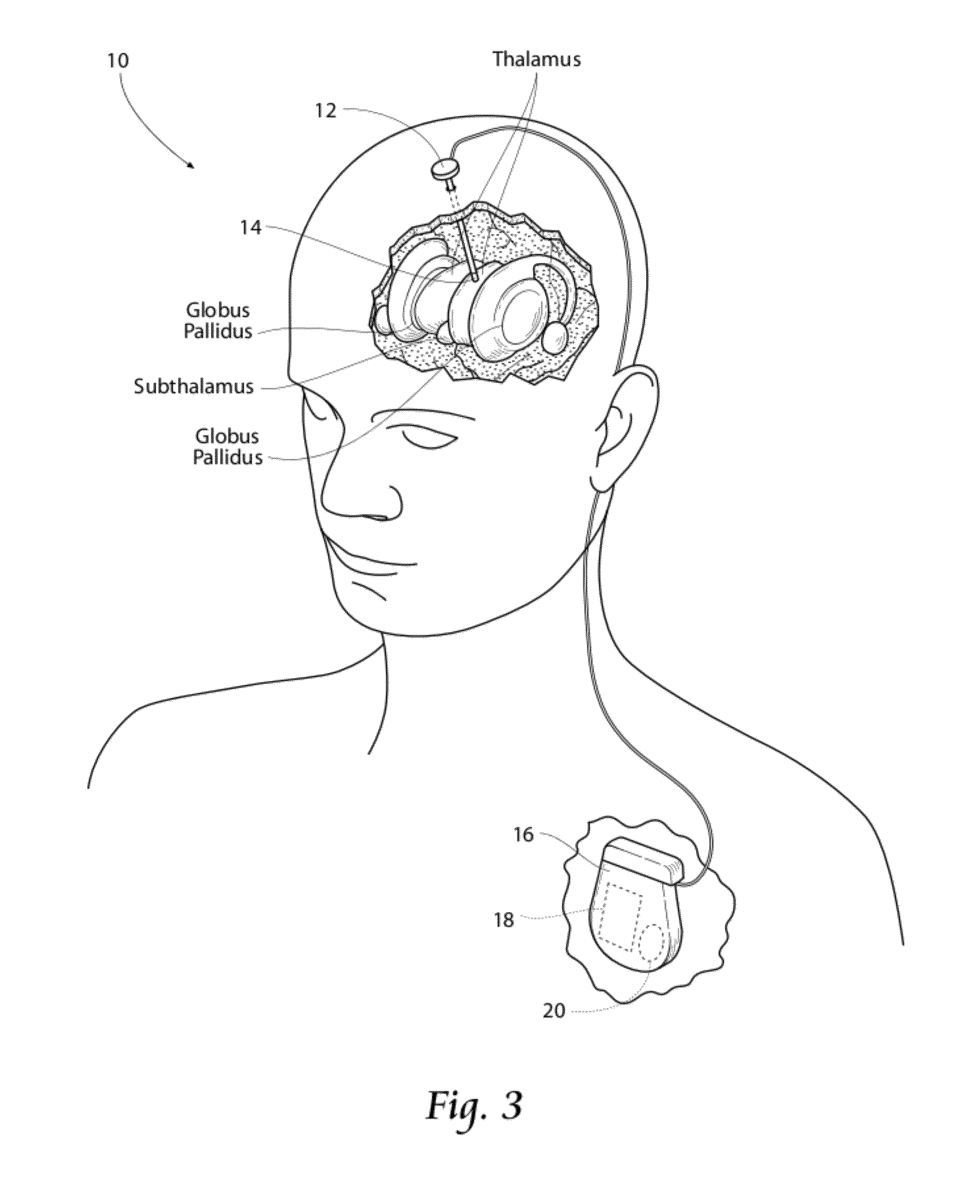
[0030]FIG. 3 is a system 10 for stimulating tissue of the central nervous system. The system includes a lead 12 placed in a desired position in contact with central nervous system tissue. In the illustrated embodiment, the lead 12 is implanted in a region of the brain, such as the thalamus, subthalamus, or globus pallidus for the purpose of deep brain stimulation. However, it should be understood, the lead 12 could be implanted in, on, or near the spinal cord; or in, on, or near a peripheral nerve (sensory or motor), in any subcutaneous tissue such as muscle tissue (including cardiac tissue) or adipose tissue for the purpose of selective stimulation to achieve a therapeutic purpose. In addition, the lead 12 may be utilized for transcutaneous stimulation where electrodes are placed, not subcutaneous, but on an outer skin surface.

[0031]The distal end of the lead 12 carries one or more electrodes 14 to apply electrical pulses to the targeted tissue region. The electri...


PUM


Abstract

Systems and methods for stimulation of neurological tissue apply a stimulation waveform that is derived by a developed genetic algorithm (GA), which may be coupled to a computational model of extracellular stimulation of a mammalian myelinated axon. The waveform is optimized for energy efficiency.

Description

RELATED APPLICATION[0001]This application claims the benefit of U.S. Provisional Patent Application Ser. No. 61 / 348,963, filed May 27, 2010, and entitled “Energy-Optimal Biphasic Waveform Shapes for Neural Stimulation,” which is incorporated herein by reference.GOVERNMENT LICENSING RIGHTS[0002]This invention was made in part with government support under NIH Grant Nos. R01 NS040894 and R21 NS054048. The government has certain rights to the invention.FIELD OF THE INVENTION[0003]This invention relates to systems and methods for stimulating nerves in mammals and, in particular, humans.BACKGROUND OF THE INVENTION[0004]Implantable and external electrical stimulators assist thousands of individuals with neurological disorders. These stimulators generate electrical waveforms, which are delivered by leads to targeted tissue regions to treat the neurological disorders. Examples of treating neurological disorders using electrical stimulation include deep brain stimulation, cortical stimulatio...

Claims


Application Information

Patent Timeline
IPC IPC(8): A61N1/378A61N1/36
CPCA61N1/0529A61N1/36146A61N1/36175A61N1/3606
Inventor GRILL, WARREN M.WONGSARNPIGOON, AMORN
Owner NDI MEDICAL
Learn More