Electronic device having compact heat radiation structure

a heat radiation structure and electronic device technology, applied in the field of electronic devices, can solve the problems of increasing the size of the device, increasing the power consumption, and the structure relying on a cooling fan is not particularly suitable for portable electronic devices, so as to prevent an increase in the size, weight and power consumption of the device, and efficiently dissipate the heat generated

Active Publication Date: 2008-02-26
NEC CORP
View PDF11 Cites 28 Cited by
  • Summary
  • Abstract
  • Description
  • Claims
  • Application Information

AI Technical Summary

Benefits of technology

[0009]It is an object of the present invention to provide an electronic device having a heat radiation structure which is capable of efficiently dissipating heat generated from high heat generating parts while preventing an increase in the size, weight, and power consumption of the device.

Problems solved by technology

However, a structure which employs a cooling fan to dissipate heat generated by high heat generating parts causes an increase in the size of a device, in order to accommodate the cooling fan therein, and an increase in power consumption.
From these requirements, the structure relying on a cooling fan is not particularly suitable especially for portable electronic devices.
On the other hand, in the structure designed to radiate heat from the housing, as described in JP-2001-166851, when the device is placed on a desk, it is possible that heat may be trapped between the desk and the device, thereby resulting in a failure to efficiently radiate the heat.
However, metal housing is disadvantageous over plastic housing in that parts contained therein are more susceptible to damage when the device is dropped, and in that the cost of parts is approximately doubled
In regard to a structure which includes a heat radiation member, conventionally, the heat radiation member must be provided exclusively for heat radiation, as disclosed in JP-2001-166851-A and JP-11-8484-A, thereby causing an increase in the size and weight of the device.

Method used


Image

  • Electronic device having compact heat radiation structure
  • Electronic device having compact heat radiation structure
  • Electronic device having compact heat radiation structure

Examples


Embodiment Construction

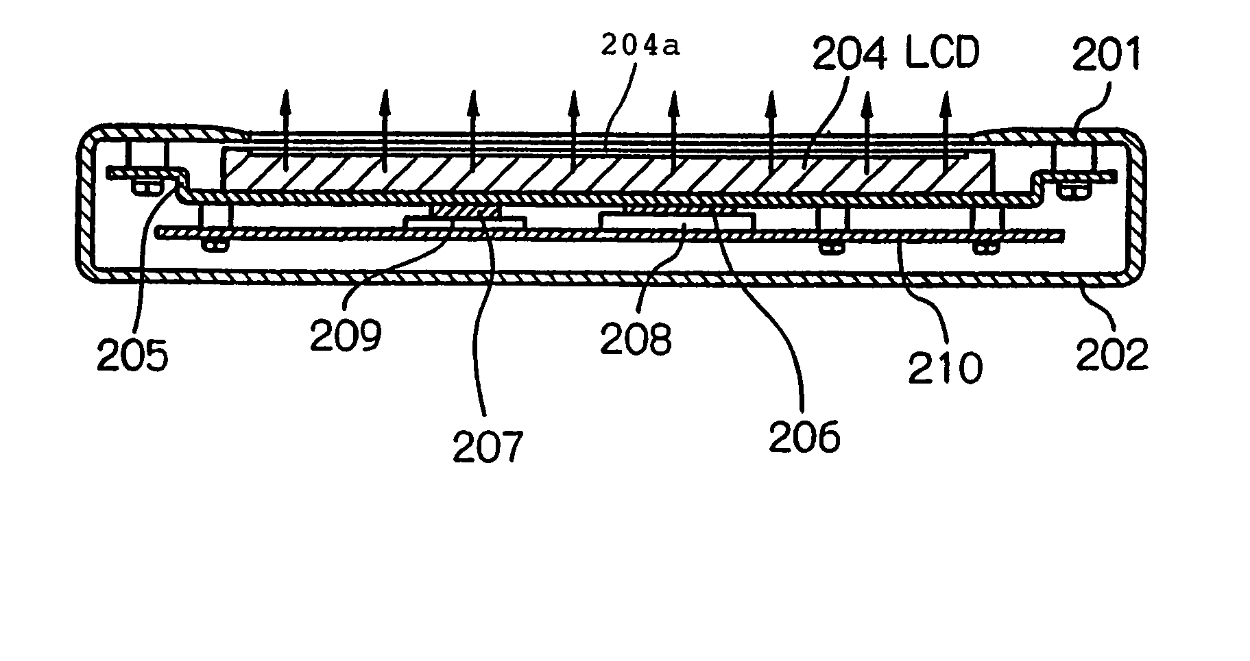
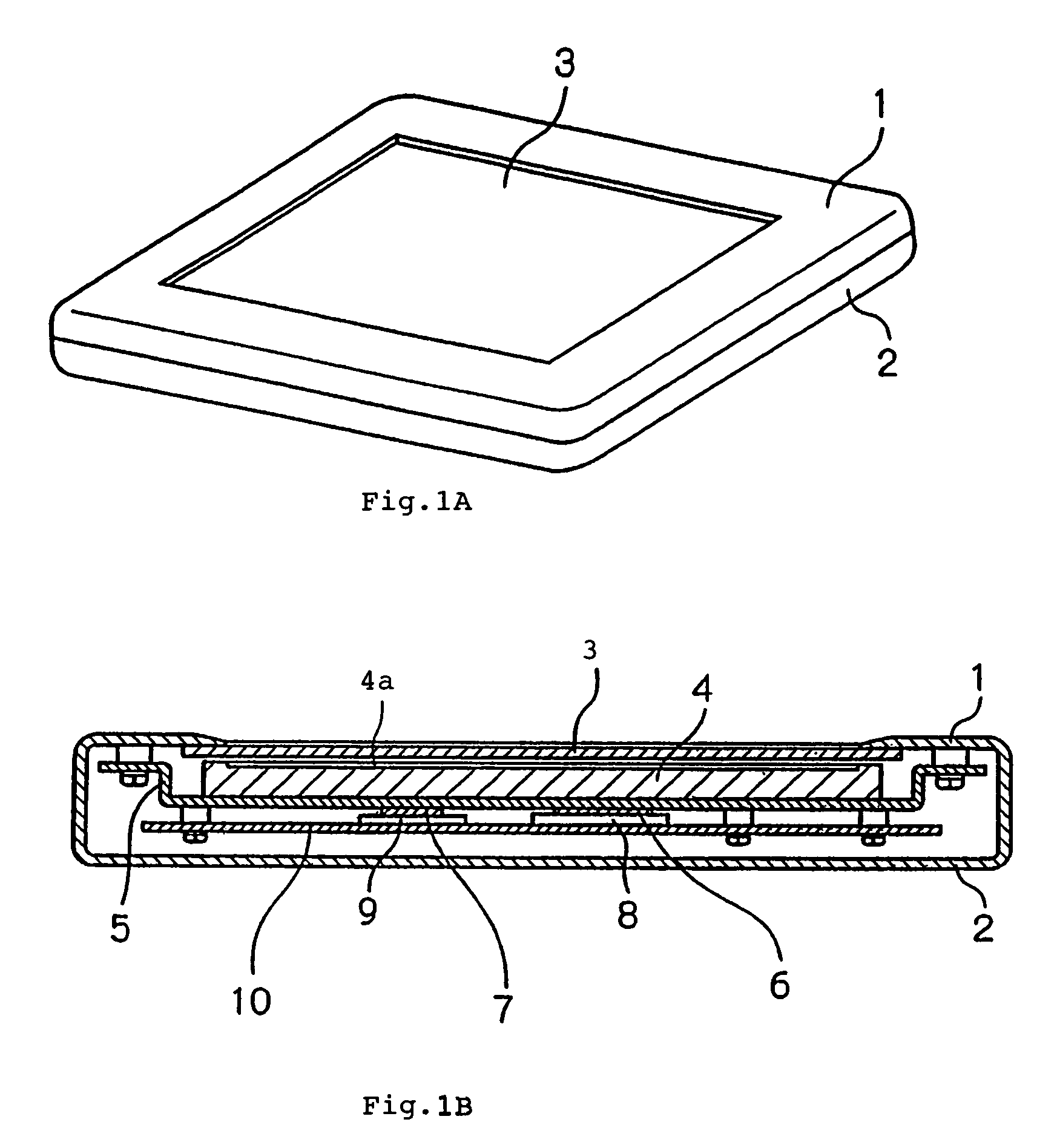
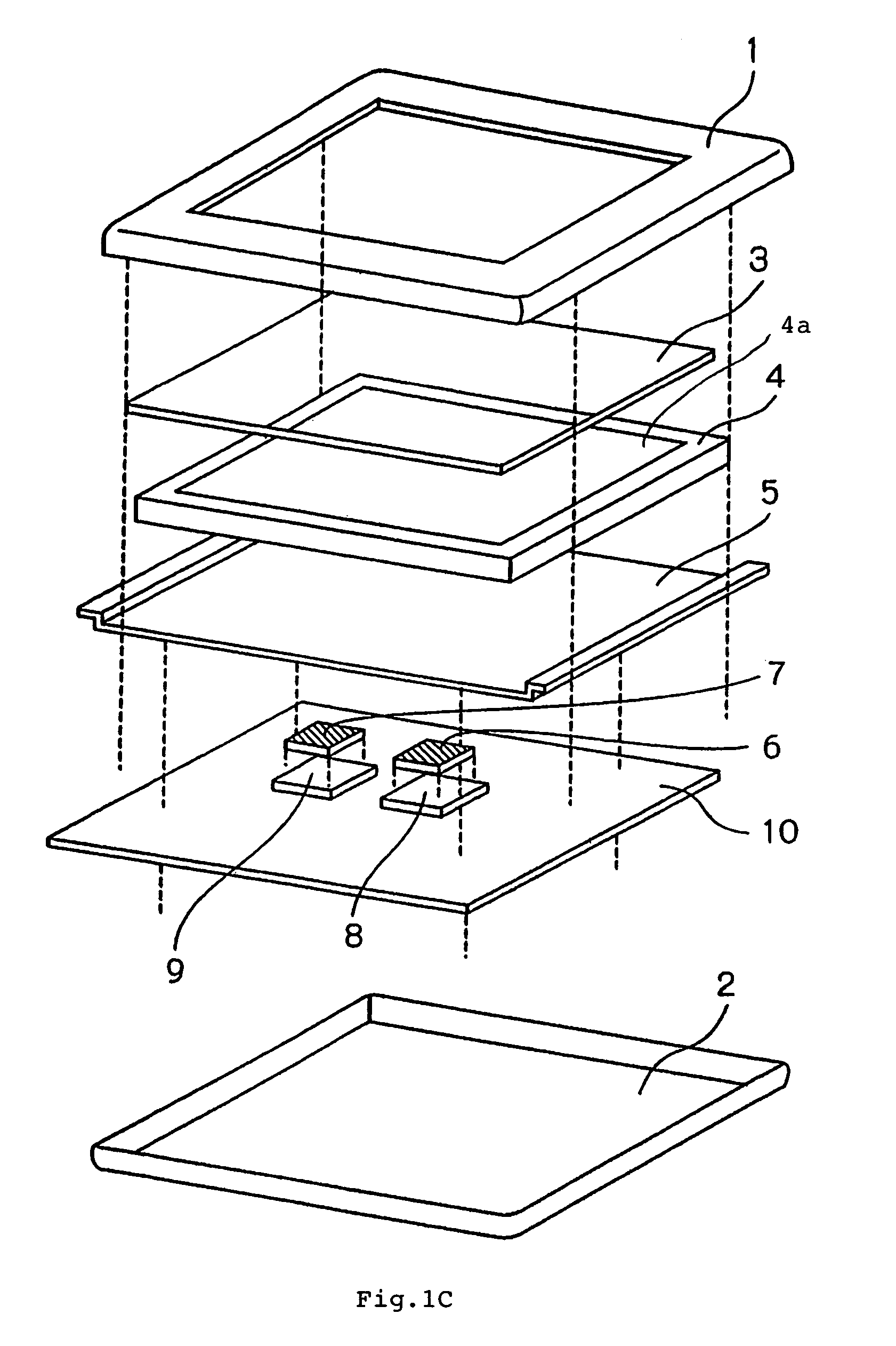
[0025]FIGS. 1A to 1C illustrate a portable electronic device according to a first embodiment of the present invention. Referring to these figures, the portable electronic device of this embodiment has LCD (liquid crystal display) 4 as a display device. Since this portable electronic device is operated by a user while the user is viewing this LCD 4, the device is normally used, as illustrated in FIG. 1A, with display panel 4a of LCD 4, which defines an image display plane, oriented upward. For convenience of description, in following explanation, the terms “upward” and “downward” correspond to the normal state of use of the device.

[0026]The portable electronic device of this embodiment is surrounded by a housing comprised of upper housing half 1 and lower housing half 2. Upper housing half 1 is formed with an opening for exposing display panel 4a of LCD 4 therethrough. More precisely, in this embodiment, touch panel 3 is disposed on LCD 4, so that it is touch panel 3 which is directl...


PUM


Abstract

A liquid crystal display (LCD) is fixed to an upper housing half by an LCD fixing frame made of a material having a high thermal conductivity. The LCD fixing frame is attached to the upper housing half in contact with a lower surface of the LCD on the opposite side of a display panel which defines an image display plane. A substrate mounted with high heat generating parts such as a CPU is attached to the LCD fixing frame such that the high heat generating parts face the lower surface of the LCD fixing frame. A thermally conductive member is disposed between the high heat generating parts and the LCD fixing frame in contact with the high heat generating parts and LCD fixing frame.

Description

BACKGROUND OF THE INVENTION[0001]1. Field of the Invention[0002]The present invention relates to an electronic device, and more particularly, to a heat radiation structure thereof.[0003]2. Description of the Related Art[0004]In electronic devices, parts, in particular, a CPU, IC's and the like generate heat as they operate. For such high heat generating parts, it is necessary to dissipate the generated heat in order to prevent the heat from adversely affecting the parts themselves and / or surrounding parts.[0005]Conventionally, known structures for dissipating heat from such high heat generating parts have relied on a fan and / or a heat radiation member having a high thermal conductivity disposed in a device. JP-2001-166851-A discloses a heat radiation structure which employs a heat radiation member for conducting heat to the housing of a device to radiate the heat to the outside from the housing. JP-11-8484-A in turn discloses a heat radiation structure which has a heat radiation win...

Claims


Application Information

Patent Timeline
Patent Type & Authority Patents(United States)
IPC IPC(8): H05K7/20
CPCG02F1/133308G02F1/133385
Inventor NISHIMURA, HIDEKITOMIZAWA, KAZUHIRO
Owner NEC CORP
Why Eureka
Try Eureka