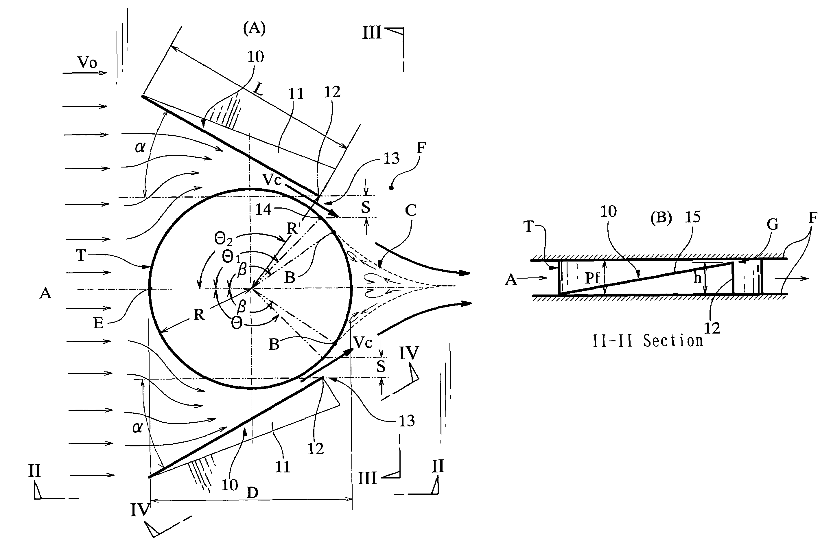
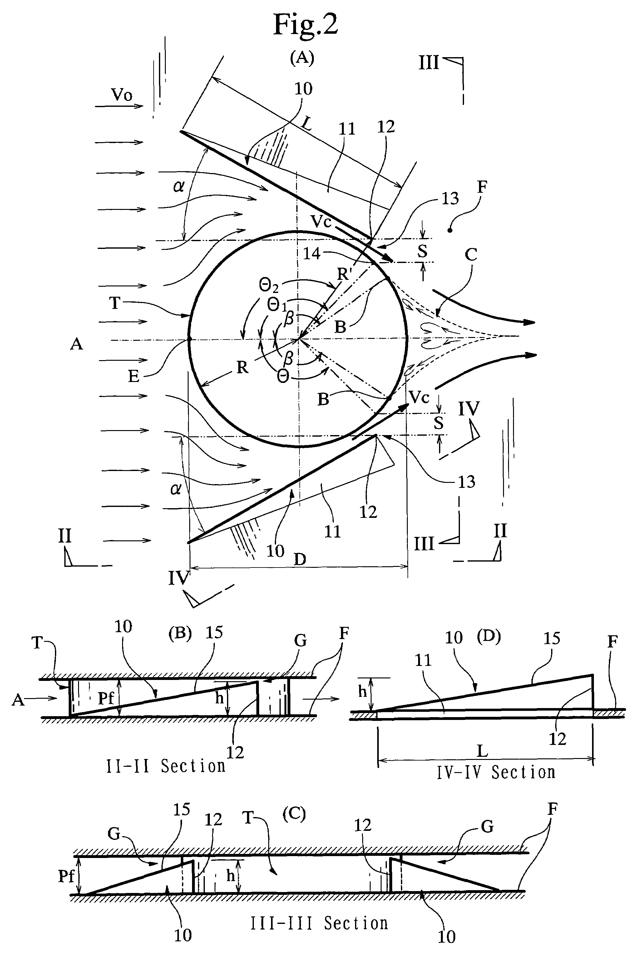
[0012]Having preserved steady efforts to the study for achieving these purposes, the present inventor confirmed that the air flow A could enter the rear of the tube by displacing the position of the aforementioned separation point B to a range of the angle β>90°, whereby the separation wake zone C could be considerably reduced or eliminated. Thus, the present inventor attained this invention, based on such findings.
[0014]said heat transfer fin provided with a guide fin, which is positioned in vicinity of said heat transfer object and oriented at a predetermined
attack angle with respect to said fluid so as to conduct the fluid to rear of said heat transfer object, thereby reducing a separation wake zone behind said heat transfer object.
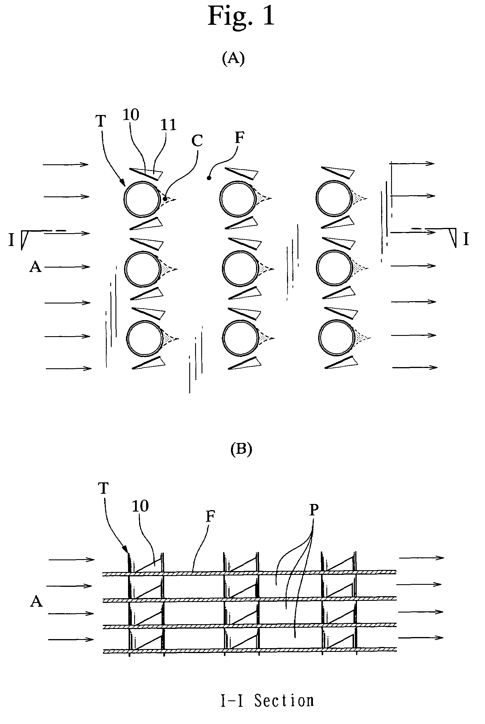
[0015]According to the arrangement of the present invention, the heat carrier fluid (A) flows through a fluid passage formed between the guide fin (10) and the heat transfer object (T), while being in heat transfer contact with the object, guide fin and heat transfer fin. The guide fin is oriented to make a predetermined
attack angle (α) with respect to the fluid, so that the fluid is conducted to the rear of the heat transfer object. The guide fin acts to reduce the separation wake zone (C) behind the tube, thereby augmenting the heat transfer of the device and also, reducing the pressure loss thereof. A part of the heat carrier fluid gets over or goes beyond the guide fin to generate a longitudinal vortex behind the guide fin. This longitudinal vortex effect causes a swirling flow to be generated in the rear of the guide fin, the swirling flow being deflected in accordance with the inclination of guide fin (the attack angle α). The swirling flow makes further improvement in the heat transfer effect of the heat transfer device without providing an excessive pressure loss in the heat transfer device.
[0016]The present invention also provides an air-cooled type of heat exchanger provided with a fan effecting compulsory draft of the heat carrier fluid and said heat transfer device as set forth above, whereby
noise caused in operation of the fan is diminished by reduction of pressure loss of said heat transfer device. Since a blast capacity of heat carrier fluid required for ensuring a predetermined heat transfer effect is lowered by augmentation of the heat transfer of the device and reduction of the pressure loss thereof, the load of fan for compulsory draft is reduced. Therefore, it is possible to reduce the
electricity consumption of fan and the
noise in the air-cooled type of heat exchanger during operation of the fan.
[0019]According to this feature of the present invention, the position of separation point is determined by setting of the attack angle, configuration, position and dimensional proportion of the guide fin. The position of separation point is a principal factor on the basis of which a manner of creation of separation wake zone behind the heat transfer object is controlled, and the condition of the separation wake zone is one of essential factors on which the heat transfer performance and pressure loss of the heat transfer device or the heat exchanger are dependent. Therefore, in accordance with the method of the present invention, the position of separation point is controlled by setting of the guide fin so that the separation wake zone behind the heat transfer object is reduced, whereby both of the heat transfer performance and the pressure loss of the heat transfer device or the heat exchanger can be improved.
[0022]In a further preferred embodiment of the present invention, the aforementioned heat transfer object is a
heat transfer tube (T) through which a thermal medium fluid to be heated or cooled can pass, and the heat transfer fins are arranged in a lengthwise direction of the tube, spaced a predetermined distance from each other. The thermal medium fluid is cooled or heated by heat exchange between the thermal medium fluid in the tube and the heat carrier fluid flowing in close vicinity of the surfaces of the tube and the heat transfer fin. The guide fins are positioned on both sides of the tube in symmetry so as to define fluid passages for the heat carrier fluid between the guide fins and the tube. The passage diverges toward the upstream side of the heat carrier fluid and converges toward an area downstream of the tube. The attack angle of the guide fin with respect to a direction of the heat carrier fluid flow is set to be a predetermined angle in a range from 5° to 60° (5°˜60°) and the downstream end of the guide fin is spaced from the tube wall of the
heat transfer tube so as to form a
narrow gap for spouting the heat carrier fluid therethrough to the rear of the tube. According to such a heat transfer device, the heat carrier fluid flows through the fluid passage formed between the tube and the guide fin while being in heat transfer contact with the tube and the heat transfer fin. The
contiguity is made in a direction of the heat carrier fluid flow by the guide fin and the tube, whereby the separation point of the heat carrier fluid is shifted to a position at an angle β>90° and the velocity of heat carrier fluid flow is accelerated so as to direct a spouting flow at a relatively
high velocity through the aforesaid gap to the rear of the tube. The heat carrier fluid flowing into the rear of the tube prevents so-called “
dead water zone” from being created behind the tube, and therefore, the separation wake zone is considerably reduced or substantially eliminated. Such reduction or
elimination of the separation wake zone results in not only augmentation of heat transfer between the tube and the heat carrier fluid, but also reduction of pressure loss of the heat carrier fluid. In general, the pressure loss tends to significantly increase in use of a heat carrier fluid of a low Reynolds number, and therefore, the present invention exhibits especially significant effects of heat transfer augmentation and pressure loss reduction in its application to a heat exchanger with use of such a heat carrier fluid.


