Clean container module

a technology of cleaning container and module, which is applied in the direction of tray containers, transportation and packaging, packaging goods types, etc., can solve the problems of difficult to clean the clean container and dry the parts of the clean container module after cleaning, and achieve satisfactory electrostatic protection, facilitate cleaning and drying maintenance work, and prevent obstruction of precision

Inactive Publication Date: 2008-03-04
IND TECH RES INST
View PDF4 Cites 7 Cited by
  • Summary
  • Abstract
  • Description
  • Claims
  • Application Information

AI Technical Summary

Benefits of technology

[0007]The present invention has been accomplished under the circumstances in view. It is therefore the main object of the present invention to provide a clean container module, which provides a reasonable effect force transferring path when carrying the load, preventing obstruction of precision due to deformation of the container body during transportation. It is still another object of the present invention to provide a clean container module, which provides a satisfactory electrostatic protection. It is still another object of the present invention to provide a clean container module, which facilitates performance of cleaning and drying maintenance works. To achieve these and other objects of the present invention, the clean container module comprises a container body, a rack, a top access board, and a bottom access board. The container body comprises an inside receiving chamber, a front opening in communication with the inside receiving chamber, a top panel, and a bottom panel. The top panel and the bottom panel of the container body each have a plurality of through holes in communication with the inside receiving chamber respectively. The rack is mounted inside the inside receiving chamber of the container body, comprising a horizontal top panel and two upright side panels perpendicularly downwardly extended from two distal ends of the horizontal top panel of the rack. The horizontal top panel of the rack has a plurality of upwardly mounting devices. The two upright side panels of the rack each have an inner side, a plurality of horizontal insertion slots arranged at different elevations at the inner, a bottom side, and a plurality of mounting devices downwardly extended from the bottom side. The top access board is provided above the top panel of the container body, comprising a plurality of fastening devices respectively inserted through the corresponding through holes of the top panel of the container body and respectively fastened to the corresponding mounting devices of the horizontal top panel of the rack. The bottom access board is provided below the bottom panel of the container body, comprising a plurality of fastening devices symmetrically disposed near the two opposite lateral sides thereof and respectively inserted through the corresponding through holes of the bottom panel of the container body and respectively fastened to the corresponding mounting devices of the two upright side panels of the rack.
[0008]The rack is inserted through the front opening of the container body into the inside of the inside receiving chamber and then fixedly fastened to the top access board and the bottom access board. Therefore, it is not necessary to make additional opening or aperture in the container body for accommodating the rack. Subject to the aforesaid design, the container body is easy to manufacture and assemble. After installation of the other parts of the clean container module, the structural strength of the container body is kept intact. Because only a limited number of through holes are formed in the container body, the inside receiving chamber can be maintained in a good airtight status after closing of the front opening of the container body, preventing exterior moisture or airborne particles from passing to the interior of the inside receiving chamber. Further, the new concept of the modularized design of the rack shows a significant effect to the improvement of the quality of the clean container module and allowing optimal use of materials, so as to lower the manufacturing cost of the clean container module. Further, because only a limited number of through holes are formed in the container body, there is no dead corner in the container body, and the container body can easily be cleaned and dried with cleaning and drying apparatus.
[0009]Further, the top access board, the rack, and the bottom access board can be made of conductive material, thereby forming an ESD (electrostatic discharge) path to ground through the machine interface. Therefore, electrostatic protection of the clean container module is well established.

Problems solved by technology

Further, due to many dead corners are created inside the container body 91, it is difficult to clean the clean container and to dry the parts of the clean container module after cleaning.

Method used


Image

  • Clean container module
  • Clean container module
  • Clean container module

Examples


Embodiment Construction

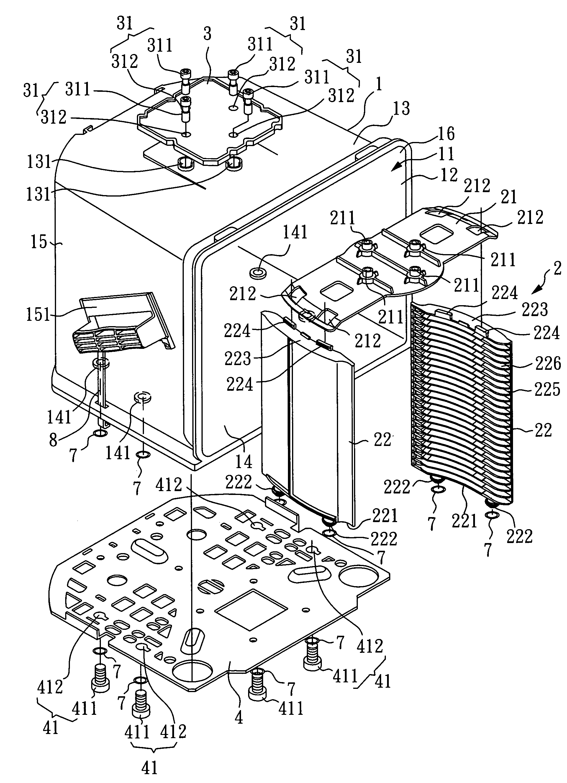
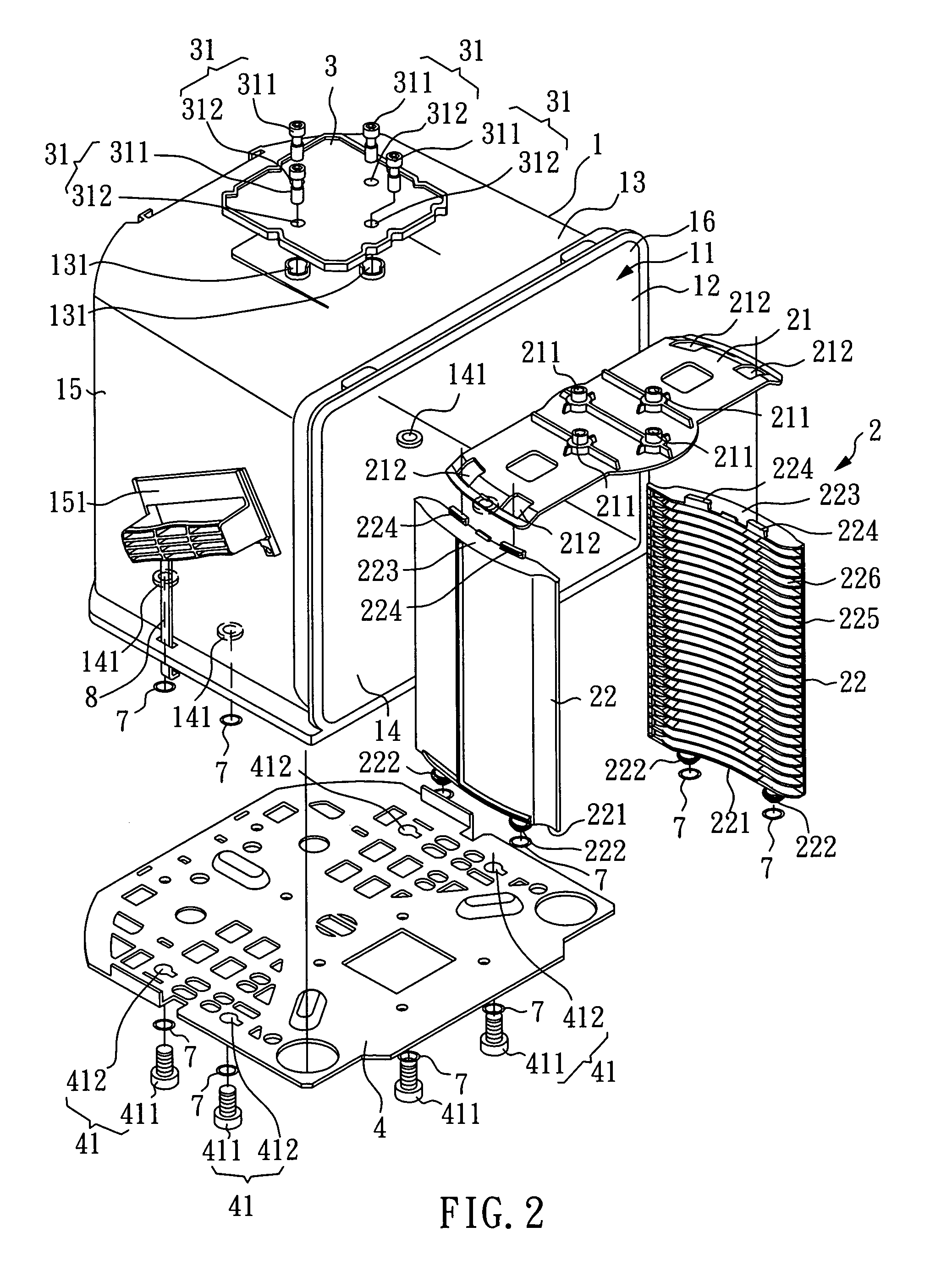
[0017]Referring to FIG. 2˜FIG. 4, a clean container module in accordance with the first embodiment of the present invention is shown comprised of a container body 1, a rack 2, a top access board 3, and a bottom access board 4.

[0018]The container body 1 comprises an inside receiving chamber 11, a front opening 12, a top panel 13, a bottom panel 14, a left-side panel 15, a right-side panel 16, a left-side handle 151 provided at the outside wall of the left-side panel 15, a right-side handle (not shown) provided at the outside wall of the right-side panel 16, a plurality of top through holes 131 through the top panel 13, and a plurality of bottom through holes 141 through the bottom panel 14.

[0019]The rack 2 according to this embodiment is a wafer cassette insertable through the front opening 12 into the inside of the inside receiving chamber 11 for holding wafers 61 inside the container body 1, comprising a transversely extended (horizontal) top panel 21 and two upright side panels 22...


PUM


Abstract

Disclosed is a clean container module, which includes a container body with a front opening, a rack inserted through the front opening into the inside of the container body, a top access board provided above the top panel of the container body, a bottom access board provided below the bottom panel of the container body, and the rack affix to the top access board and the bottom access board. Therefore, the rack, the top access board, and the bottom access board can provide a reasonable effect force transferring path when carrying the load, preventing obstruction of precision due to deformation of the container body during transportation. Further, the rack, the top access board, and the bottom access board can provide a satisfactory electrostatic protection.

Description

BACKGROUND OF THE INVENTION[0001]1. Field of the Invention[0002]The present invention relates to a cleaning container module and more particularly, to a robust, precise, airtight, electrostatically protective clean container module, which provides a reasonable effect force transferring path when carrying the load, preventing obstruction of precision due to deformation of the container body and ESD protection function during process transportation, and storage.[0003]2. Description of Related Art[0004]In a SMIF (Standard Mechanical Interface) semiconductor factory or foundry, wafer cassettes are commonly used for carrying wafers in horizontal at different elevations. A wafer cassette has a number of support flanges for bearing wafers in horizontal at different elevations. The wafer cassette is set in a clean container module, and then the cover of the clean container module is closed to protect loaded wafers against contaminants such as, moisture in cleanroom and other environment and...

Claims


Application Information

Patent Timeline
Patent Type & Authority Patents(United States)
IPC IPC(8): A47F7/00
CPCH01L21/67386H01L21/67396
Inventor WU, TZONG-MINGHO, TIEN-LU
Owner IND TECH RES INST
Why Eureka
Try Eureka