Adjustable focus lenses

a focus lens and adjustment technology, applied in the field of adjustable focus lenses, can solve the problems of not detecting residual aberration in the human eye, difficult to focus comfortably at a near distance, and difficulty in clear, comfortable near-distance focus,

Inactive Publication Date: 2008-03-04
QUEXTA
View PDF4 Cites 56 Cited by
  • Summary
  • Abstract
  • Description
  • Claims
  • Application Information

AI Technical Summary

Problems solved by technology

The two lenses do not perfectly cancel, but as long as the power is fairly weak (i.e., less than about 5 diopters), the human eye does not detect the residual aberration.
After age 40 in most people (and by age 45 in virtually all people) a clear, comfortable focus at a near distance becomes more difficult with eyes that see clearly at a far distance.
Unless one is nearsighted, it is not possible to focus objects (such as a printed page) clearly at even an arm's length distance.
Glasses can be specially made to fit each person's prescription, but this would be expensive and time consuming.
The bigger variety in the stock of lenses the closer the needs can be matched in general but also the larger the stock the more expensive it is to maintain the stock.
Bifocals, trifocal and continuous focus glasses all have their problems as is well known by the people who wear them, and the automatic focus glasses have not been successful in solving the problems.
Surgery can correct vision problems in many cases, but eye surgery is expensive and many people who can afford eye surgery, prefer to avoid it.

Method used


Image

  • Adjustable focus lenses
  • Adjustable focus lenses
  • Adjustable focus lenses

Examples


first proposed embodiment

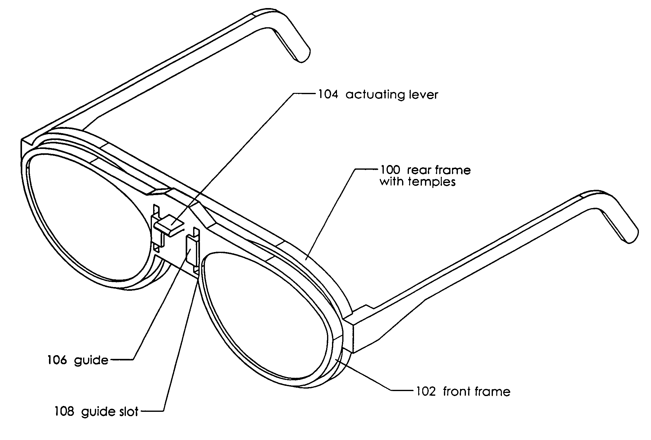
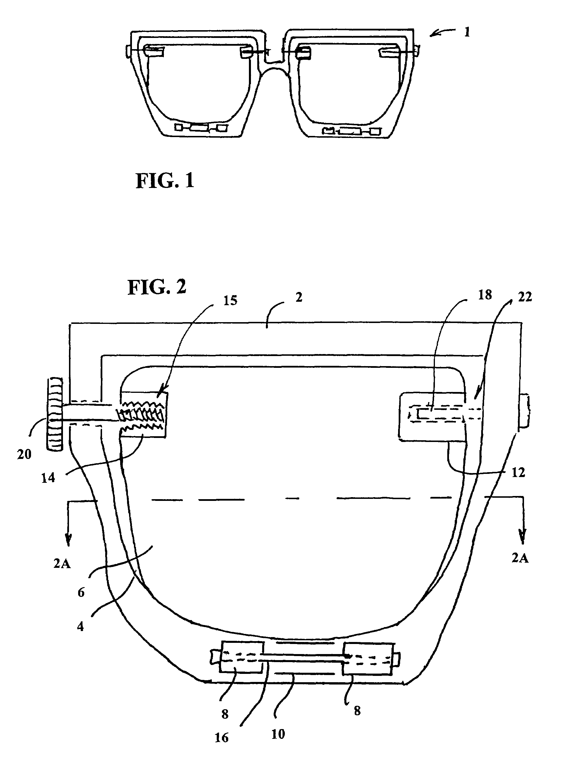
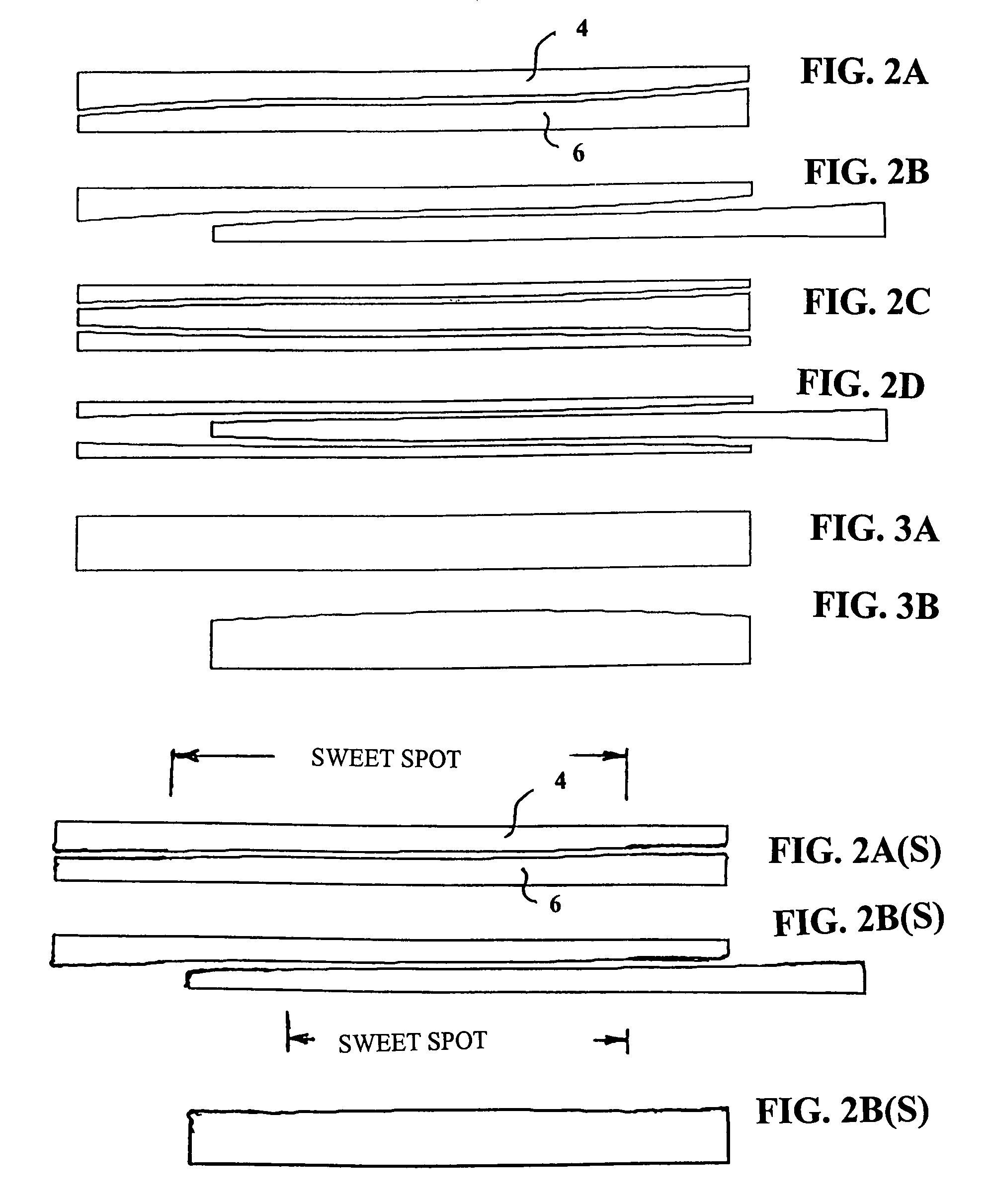
[0038]A first proposed version of the present invention is shown at 1 in FIG. 1. This is a drawing of a pair of eyeglasses with wearer operated focusing lenses. This embodiment includes metal or plastic frame 2, two back lenses 4 and two front lenses 6. Back lenses 4 are mounted rigidly on frame 2. A more detailed version of each lens pair is shown in FIG. 2. Front lenses 6 are mounted so that they can be moved laterally with respect to back lenses 4. Two pen mounts 8 are attached rigidly to frame 2 and tabs 10, 12 and 14 are attached rigidly to front lenses 6. Pen 16 passes through pen mounts 8, allowing it to slide through tab 10. Pen 18 passes through frame 2, allowing it to slide through tab 12. Adjustment screw 20 passes through frame 2 and screws into treaded socket 15 in tab 14. Spring 22 between frame 2 and tab 12 provides a compressive force in the direction of adjustment screw 20. The wearer of the glasses shown in FIG. 1 adjusts the focus of each of the lenses by rotating...

specific example

[0040]Applicant has performed ray trace calculations of the sliding lens system to verify that the optical quality is sufficient for eyewear. As an example calculation, Applicant used a pair of optics with one flat surface and one cubic surface. The flat surfaces are on the outside and the cubic surfaces are facing each other such that there is a 0.1 mm gap between the optics when in the null position, with the effect of the cubic surfaces nearly canceling each other out. The optics are assumed to be made of a typical glass with index of refraction of 1.5. The strength of the cubic surface is described by:

[0041]Z=160⁢⁢cm2⁢(x33+xy2)

[0042]The eye was modeled as having pupil diameter of 4 mm, with the pair of optics placed 2 cm in front of the eye. The eye is pointed to look at an object directly in front of the subject, with the center of the eye 3 cm from the centerline of the subject. The eyeball diameter was assumed to be 4 cm. The rays originate at the eye and travel to a plane at...


PUM


Abstract

A lens unit with two lens elements each having special surfaces such that an adjustment of the position of one of the two lens elements relative to the other in a direction generally perpendicular to a viewing direction changes the focusing power of the lens unit. In preferred embodiments two lens units are mounted in a frame to provide eyeglasses with adjustable focus. Several frame designs are described. In preferred embodiments two lens units, each lens unit having two lens elements are mounted in a frame to provide eyeglasses with adjustable focus. Several designs are described. Some designs provide for movement side to side movement of the lens elements relative to each other. In other designs the relative motion is up and down. A simple technique is a thumbscrew adjustment that is operated by the wearer. Another design is based on finger force against a friction force. In some preferred embodiments separate frames holding the lens elements pivot about pivot points on the earpiece of a support frame. In other designs two rear lens elements are mounted in a support frame and the front lens elements are mounted in a separate frame that pivots about a point on the earpiece of the support frame. Another design includes a torsion bar assures that the movements of each lens element in one of the lens units is the same as the movements of the lens elements in the other lens unit. Techniques for automatic focusing of the lenses are also disclosed. Techniques for automatic focusing of the lenses are also disclosed.

Description

[0001]This Application is a continuation in part of U.S. patent application Ser. No. 11 / 085,436 filed Mar. 21, 2005 and Ser. No. 11 / 243,944 filed Oct. 5, 2005, now U.S. Pat. No. 7,232,217 which are incorporated by reference herein and claims the benefit of Provisional Patent Application Ser. No. 60 / 688,092 filed Jun. 6, 2005. This invention relates to lenses and in particular to eyeglasses lenses and in particular to adjustable focus lenses and to processes for making eyeglass lenses.BACKGROUND OF THE INVENTIONNearsightedness and Farsightedness[0002]Nearsightedness is a condition of the eye in which distance objects cannot be focused on the retina and farsightedness is a condition of the eye in which near objects cannot be focused on the retina. These conditions are normally corrected by spectacle lenses having a power needed to correct the eye's focus error.Astigmatism[0003]Astigmatism is a condition of the eye caused by an irregular curvature of an eye surface, usually the front s...

Claims


Application Information

Patent Timeline
Patent Type & Authority Patents(United States)
IPC IPC(8): G02C7/02G02B7/02G02C7/10
CPCG02C7/02G02C7/06G02C7/061G02C7/081G02C9/00G02C9/02G02C2202/16
Inventor SPIVEY, BRETT
Owner QUEXTA
Why Eureka
Try Eureka