Pump for the transporting of fluids and of mixtures of fluids

a technology for pumping and fluids, applied in the direction of leakage prevention, motors, liquid fuel engines, etc., can solve the problems of complex design, sensitive reaction, and irritation of the comparatively long construction of the smooth restrictor part, and achieve the effect of simple, robust and compact design, and less sensitive reaction

Inactive Publication Date: 2008-03-04
SULZER MANAGEMENT AG
View PDF22 Cites 14 Cited by
  • Summary
  • Abstract
  • Description
  • Claims
  • Application Information

AI Technical Summary

Benefits of technology

[0004]It is an underlying object of the present invention to make available a pump for the transporting of fluids and / or mixtures of fluids with a proportion of solid material which avoids the disadvantages of the prior art and which is fitted with restrictor gap seals, in particular restrictor gap seals with relatively simple, robust and compact designs, which can be designed for small leakage amounts and are less sensitive with respect to production tolerances and to changes in temperature and rotational speed and which have a comparatively low service effort.
[0013]The pump in accordance with the invention has the advantage that the length of the pump, and in particular of the relief piston for the axial thrust compensation, can be shortened; the clearance between the relief piston and the housing is less critical and the leakage amounts in the region of the relief piston can be reduced. Furthermore, the pump in accordance with the invention is relatively less sensitive with respect to changes in temperature and rotational speed and to vibrations and allows a simple and robust design of the dynamic shaft seals. The comparatively low service effort for the restrictor gap seals is also advantageous.

Problems solved by technology

The restrictor gap seals of the prior art all have their specific disadvantages; e.g. the leakage amount of the smooth restrictor gap is relatively large, the clearance between the housing and the rotatable parts is critical and the comparatively long construction of the smooth restrictor part is irritating.
It is disadvantageous in the face seals that they are of complex design and react sensitively to changes in temperature and rotational speed.
In pumps with multiphase mixtures, in particular multiphase mixtures with a proportion of solid material, there is a further difficulty in that the abrasive effect of the solids has a noticeable effect on the service frequency and service life of the restrictor gap seals.

Method used


Image

  • Pump for the transporting of fluids and of mixtures of fluids
  • Pump for the transporting of fluids and of mixtures of fluids
  • Pump for the transporting of fluids and of mixtures of fluids

Examples


Embodiment Construction

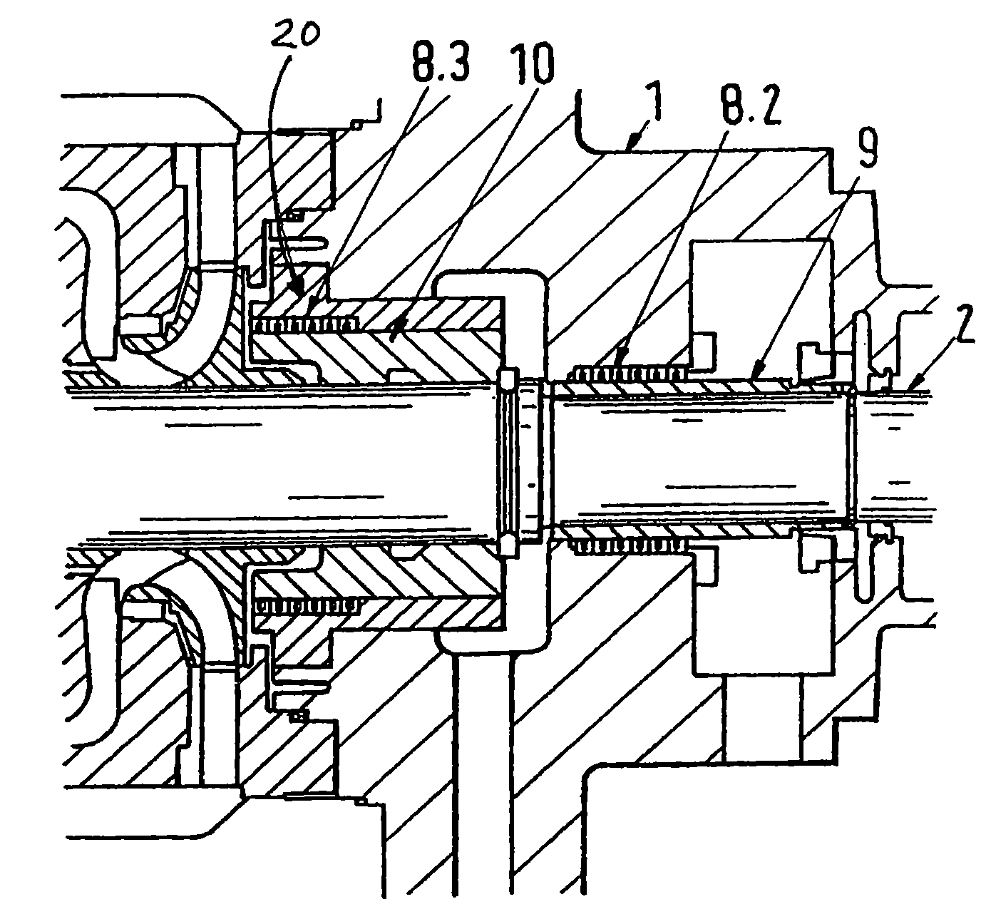
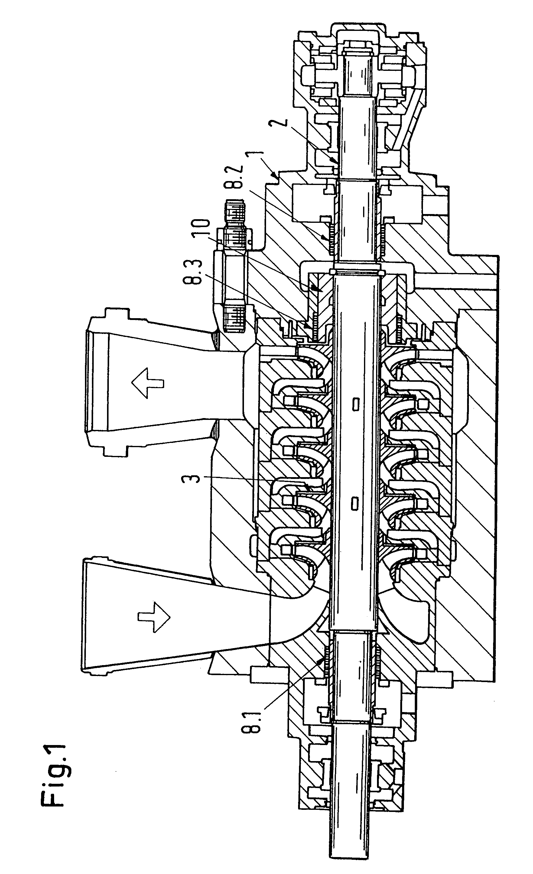
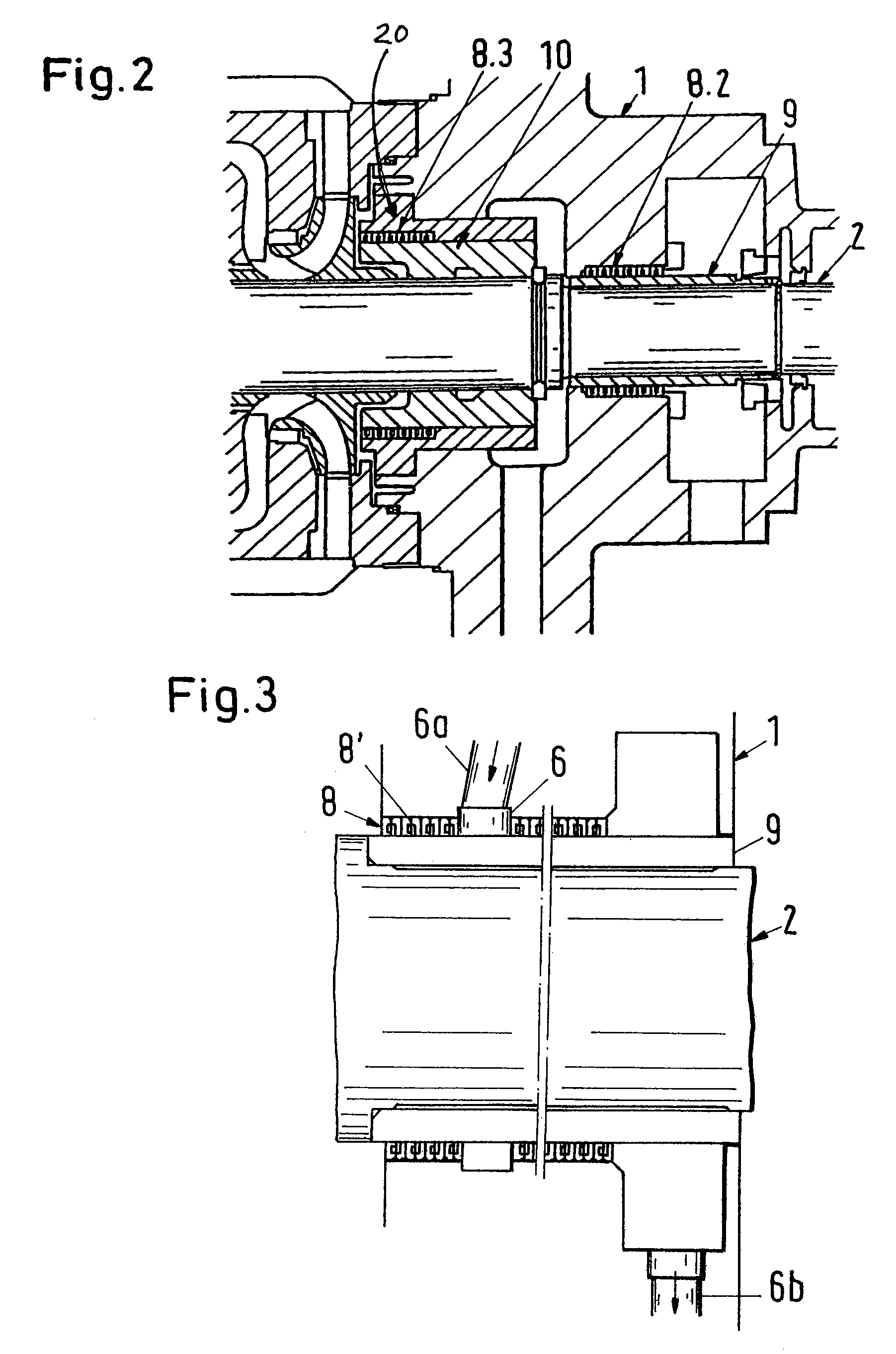
[0021]FIG. 1 shows a longitudinal section through a pump in accordance with an embodiment relating to the present invention. In FIG. 1, reference numeral 1 designates a housing, reference numeral 2 a shaft which is rotatably arranged in the housing 1, and reference numeral 10 a relief piston for the axial thrust compensation which is connected to the shaft 2 such that it rotates along on a rotation of the shaft. The shaft 2 is fitted with impellers 3. Since pressure compensation flows along the shaft and along the relief piston reduce the pump power and pollute the environment in dependence on the medium transported, restrictor gaps are provided between the housing and the shaft or between the housing and the relief piston respectively in order to limit the flow losses along the shaft and along the relief piston. Furthermore, restrictor gap seals are provided in the regions to reduce the pressure in the restrictor gaps along the pump shaft or along the relief piston respectively and...


PUM


Abstract

A pump for the transporting of fluids and / or of mixtures of fluids includes a housing (1) and at least one restrictor gap seal which is provided in the housing (1) to reduce the pressure in a restrictor gap along a rotatable part (2) of the pump, wherein the restrictor gap seal is formed as a brush seal arrangement (8). The brush seal arrangement (8) contains one or more individual brush seals (8′) which include as sealing members a plurality of sealingly arranged fibers, bristles and / or wires (8a) which are distributed and fastened in ring form and whose free ends extend towards the surface to be sealed.

Description

BACKGROUND OF THE INVENTION[0001]The invention relates to a pump for the transporting of fluids and / or of mixtures of fluids with a proportion of solid material, comprising a housing and at least one restrictor gap seal which is provided in the housing to reduce the pressure in a restrictor gap along a rotatable part of the pump.[0002]Centrifugal pumps are also used for the transporting of fluids and of mixtures of fluids with a proportion of solid material such as multiphase mixtures of oil, gas, water and sand, such as occur in the transporting of crude oil and natural gas. Such a pump includes a pump shaft fitted with impellers, which are rotatably arranged in a housing, as well as a relief piston for the axial thrust compensation which is connected to the pump shaft such that it rotates along on the rotation of the pump shaft. So that the pump shaft and the relief piston are freely rotatable in the housing and, on the other hand, pressure compensation flows along the rotatable p...

Claims


Application Information

Patent Timeline
Patent Type & Authority Patents(United States)
IPC IPC(8): F04D29/12F04D7/04F04D7/06F16J15/32F16J15/34
CPCF04D7/06F04D29/128F16J15/3288F16J15/3404F04D1/063
Inventor MEUTER, PAUL
Owner SULZER MANAGEMENT AG
Why Eureka
Try Eureka