Dust collection system for a belt sander

a belt sander and dust collection technology, which is applied in the direction of grinding machines, grinding/polishing apparatuses, manufacturing tools, etc., can solve the problems of reducing access, vision, and balance, and achieve the effect of improving dust removal airflow and more efficient dust collection

Inactive Publication Date: 2008-03-04
BLACK & DECKER INC
View PDF44 Cites 9 Cited by
  • Summary
  • Abstract
  • Description
  • Claims
  • Application Information

AI Technical Summary

Benefits of technology

[0010]In one preferred form, the present invention provides a sander with a separate dust collection fan driven off the main motor, but not directly connected to it. This dust fan can be located away from the motor for a more compact tool and improved dust removal airflow. Moreover it can be spun at a speed independent of the motor armature and more efficient for dust collection. In a preferred embodiment the dust fan is powered from the main motor by means of a belt drive, but a gear train could also be used.
[0011]The separate fan system can be turned off by either of two convenient methods. A user operable damper may be provided in the dust flow path to interrupt the airflow even though the fan continues to spin. Unlike the single motor single fan designs, this will have no adverse effect on cooling the motor. Alternatively, the dust fan can be disconnected from the motor, thus permanently disabling the dust collection system, unloading the motor, and decreasing tool noise.
[0012]In another preferred embodiment, the sander is provided with a semi-rigid dust cassette that is mounted low and rearward of the sander. Thus located, it reduces tool access and user vision problems. Moreover, the dust fan does not have to blow dust upward into a fabric sack that is held open only by the air pressure within. Additionally, so located and constructed the preferred dust receptacle / cassette reduces the access, vision, and balance problems associated with the “flag bag” type receptacles.
[0013]In the preferred embodiment, the dust receptacle comprises a flexible part of rubber like material. Thus constructed, the flexible part of the dust receptacle can be deformed in order to facilitate alignment and engagement of the dust receptacle when mounting it to the sander.
[0014]In another aspect of the preferred embodiment, secure engagement is further enhanced by the provision of a positive locking mechanism for holding together the dust outlet of the sander housing and the inlet of the dust receptacle. The locking mechanism comprising a movable collar on the outlet duct of the housing which lockably engages tabs on the inlet nozzle of the dust receptacle.

Problems solved by technology

Additionally, so located and constructed the preferred dust receptacle / cassette reduces the access, vision, and balance problems associated with the “flag bag” type receptacles.

Method used


Image

  • Dust collection system for a belt sander
  • Dust collection system for a belt sander
  • Dust collection system for a belt sander

Examples


Embodiment Construction

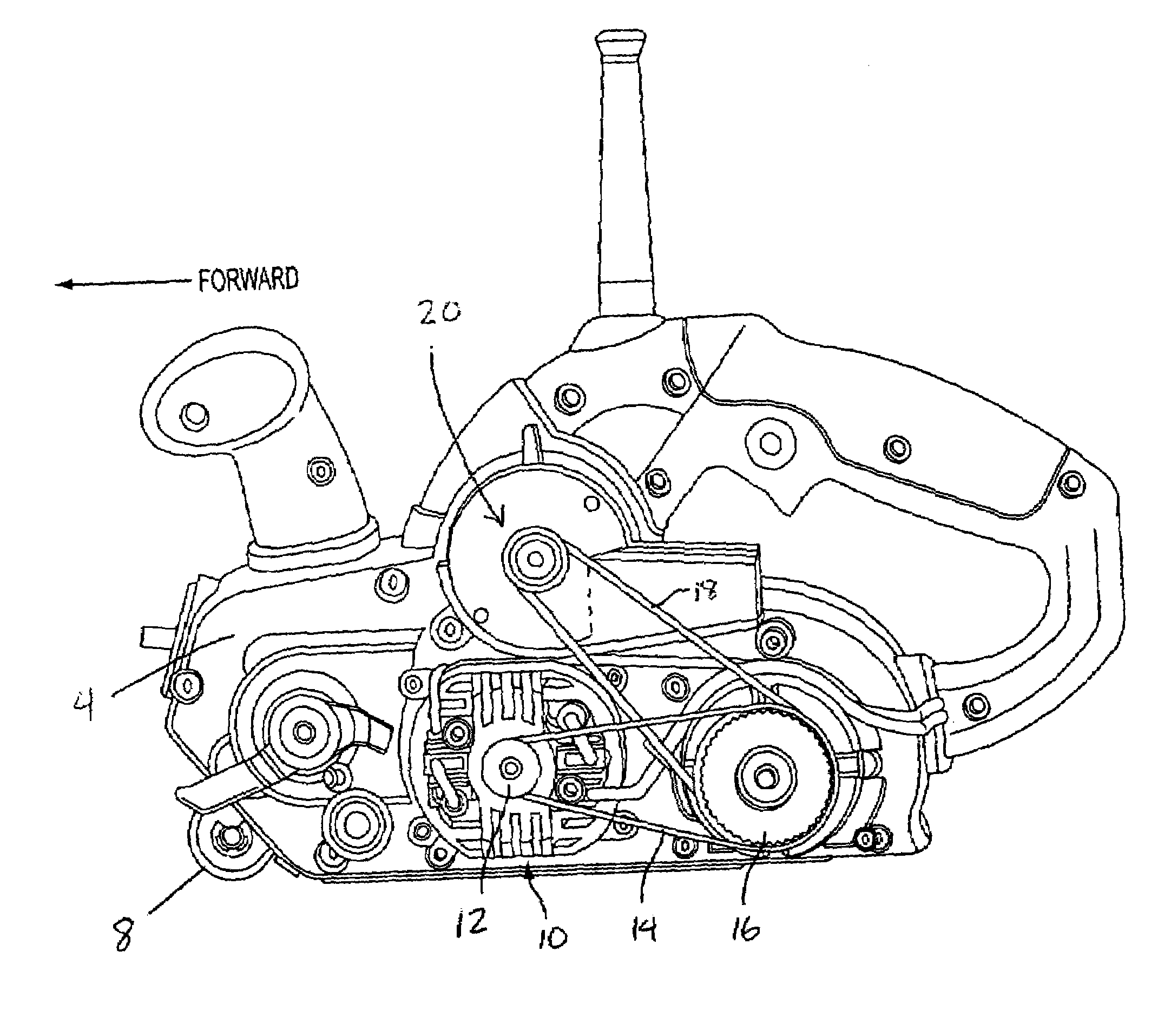
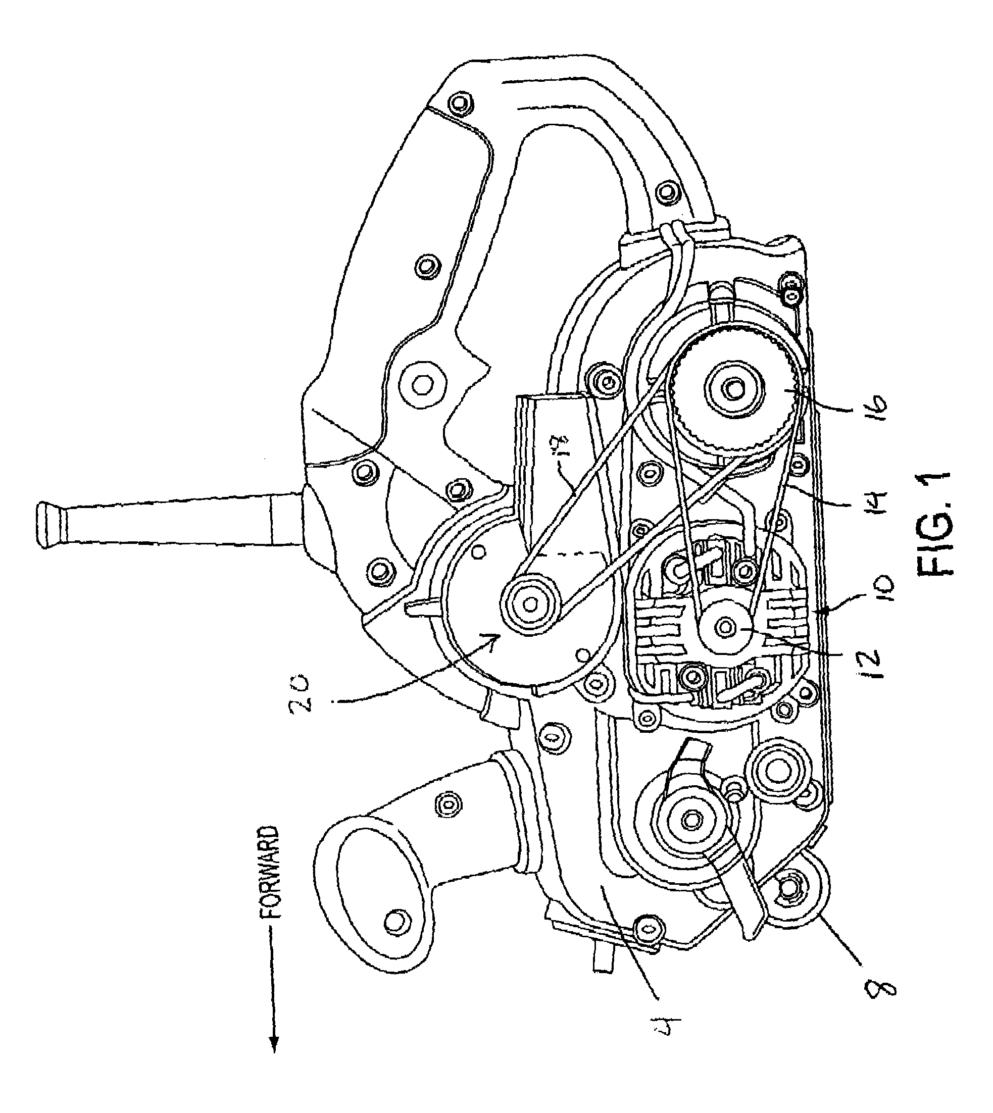
[0037]With reference to the accompanying FIGS. 1, 2, 3, and 4, motor assembly 10 is transversely mounted between the rearwardly located drive roller 9 and the front roller assembly 8. The motor output shaft, which extends through an opening in gear case cover 4, ends in drive pulley 12.

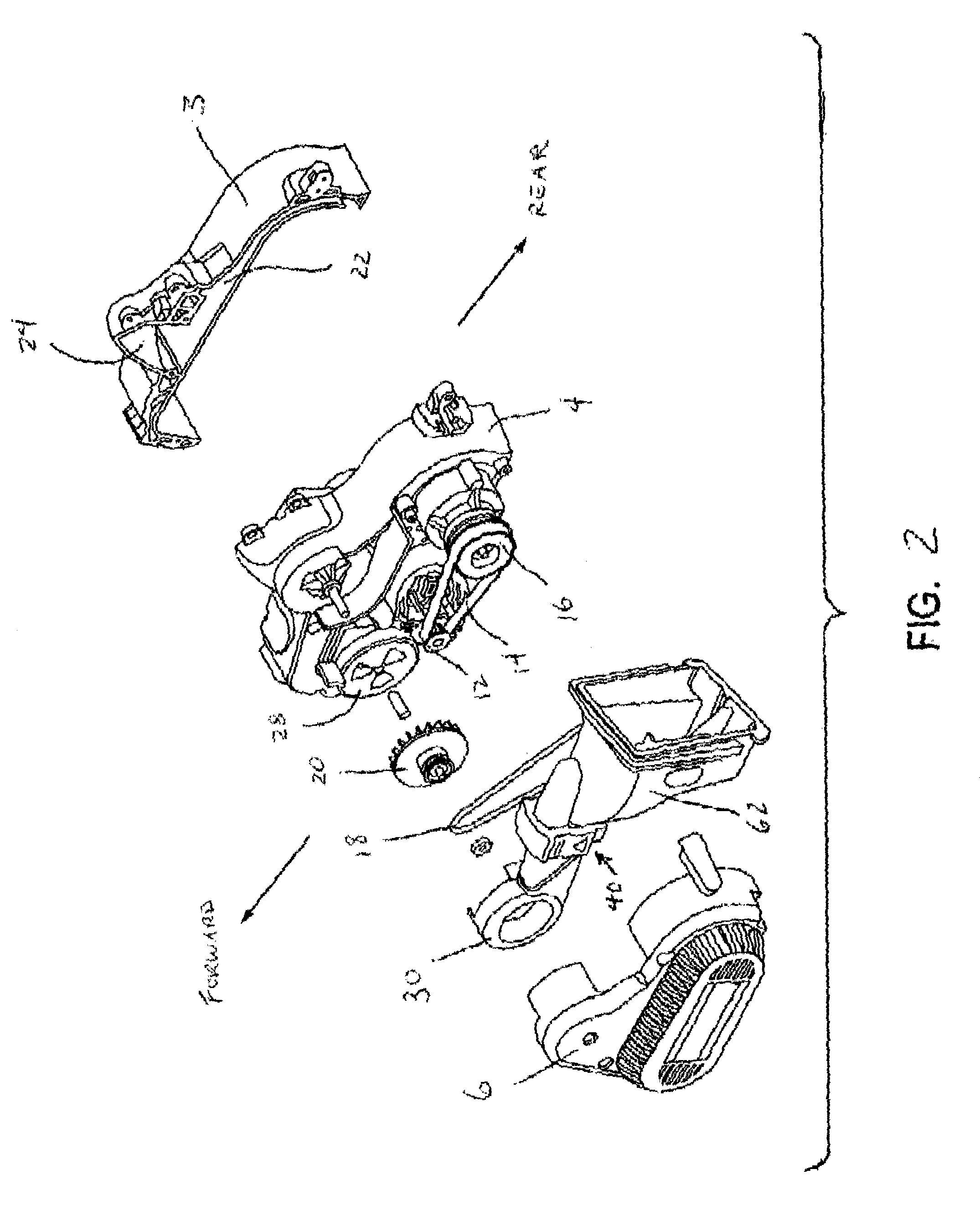
[0038]Drive pulley 12 pulls drive belt 14. Drive belt 14 turns driven pulley 16. Driven pulley 16, through gearing not shown, turns rear drive roller 9. A second portion of driven pulley 16 pulls dust collection fan belt 18, which powers a dust collection fan 20 that is located on an upper portion of gear case cover 4. In the preferred embodiment shown, fan belt 18 is an o-ring.

[0039]With particular reference to FIGS. 2-4, the left-hand / outward side of the gear case cover 4 is covered by belt cover / housing 6, which encloses the pulleys 12 and 16 and belts 14 and 18. Completing the frame / superstructure of the sander is the right side housing 3.

[0040]With additional reference to FIGS. 5-7, the suction c...


PUM

PropertyMeasurementUnit
distanceaaaaaaaaaa
transmissionaaaaaaaaaa
flexibleaaaaaaaaaa

Abstract

An electrically powered belt sander comprising a housing, a dust flow path defined by the housing, a motor mounted in the housing at a first location and having an output shaft, a fan connectable to the motor output shaft and rotateably mounted in the housing at a second location a distance from the motor output shaft, a belt connectable between the motor output shaft and the fan whereby the rotation of the motor output shaft drives the rotation of the fan, and a damper located in the dust flow path and operable for blocking the dust flow path.

Description

FIELD OF THE INVENTION[0001]The present invention generally relates to electric powered portable sanders having a dust collection system. More particularly it relates to portable belt sanding power tools.BACKGROUND OF THE INVENTION[0002]All sanding tools create a large amount of dust. In particular, a belt sander creates large quantities of wood dust both in the air and on the surface of the workpiece. Because of this most electric sanders employ some sort of dust collection system. These dust collection systems typically use a fan driven directly by the motor to create a suction for the dust collection system. The dust collection fan may be half of a two-sided or double sided fan (the other half cooling the motor) or it may be mounted on one end of a motor opposite to the other end bearing a motor cooling fan. In either case, dust laden air is deliberately routed past the motor and dust leakage into the motor is aggravated.[0003]Furthermore, these systems tend to clog due to the to...

Claims


Application Information

Patent Timeline
Patent Type & Authority Patents(United States)
IPC IPC(8): B24B23/00B24B23/06B24B55/10
CPCB24B23/06B24B55/107
Inventor MELVIN, JASON R.WALSTRUM, MICHAEL J.MERHAR, III, CARL F.RICE, GREGORY A.MCKIBBEN, JOHNGAYLE, DANIELLE V.MYERBERG, JONAH
Owner BLACK & DECKER INC
Why Eureka
Try Eureka