Hydroelectric wave-energy conversion system

a technology of hydroelectric wave energy and conversion system, which is applied in the direction of electric generator control, machines/engines, mechanical equipment, etc., to achieve the effects of less pollution and contamination, less expensive, and less pollution and contamination

Active Publication Date: 2008-03-04
STRATEGIC DESIGN FEDERATION W LLC
View PDF18 Cites 20 Cited by
  • Summary
  • Abstract
  • Description
  • Claims
  • Application Information

AI Technical Summary

Benefits of technology

[0006]The present invention solves the abovementioned problems by providing an apparatus and method for generation of energy from waves in a simple and straightforward way. In comparison with the prior art, the present invention provides a less expensive system, increased reliability since waves are present day and night, less pollution and contamination, reduction of external energy sources like fuel oil. The present invention is could also be combined with solar, thermal and / or wind power where warranted by weather conditions. In addition, with some modifications the inventive apparatus and system could also be implemented in commercial ships.
[0007]The present invention captures the kinetic energy of the sea waves and converts it to electrical power. This electricity may be used to provide or supplement at least part of the existing power grid. Thus, the sea surface waves may prove to be a continuous, renewable, inexpensive and nonpolluting alternate energy source.

Problems solved by technology

However, depletion and pollution are the biggest financial and environmental concerns for society.

Method used


Image

  • Hydroelectric wave-energy conversion system
  • Hydroelectric wave-energy conversion system
  • Hydroelectric wave-energy conversion system

Examples


Embodiment Construction

[0020]This specification and the accompanying drawings disclose several preferred embodiments as examples of the invention. The invention is not intended to be limited to the embodiments illustrated. Numerous modifications, changes, variations, substitutions and equivalents will be apparent to those skilled in the art without departing from the spirit and scope of the present invention as described in the claims.

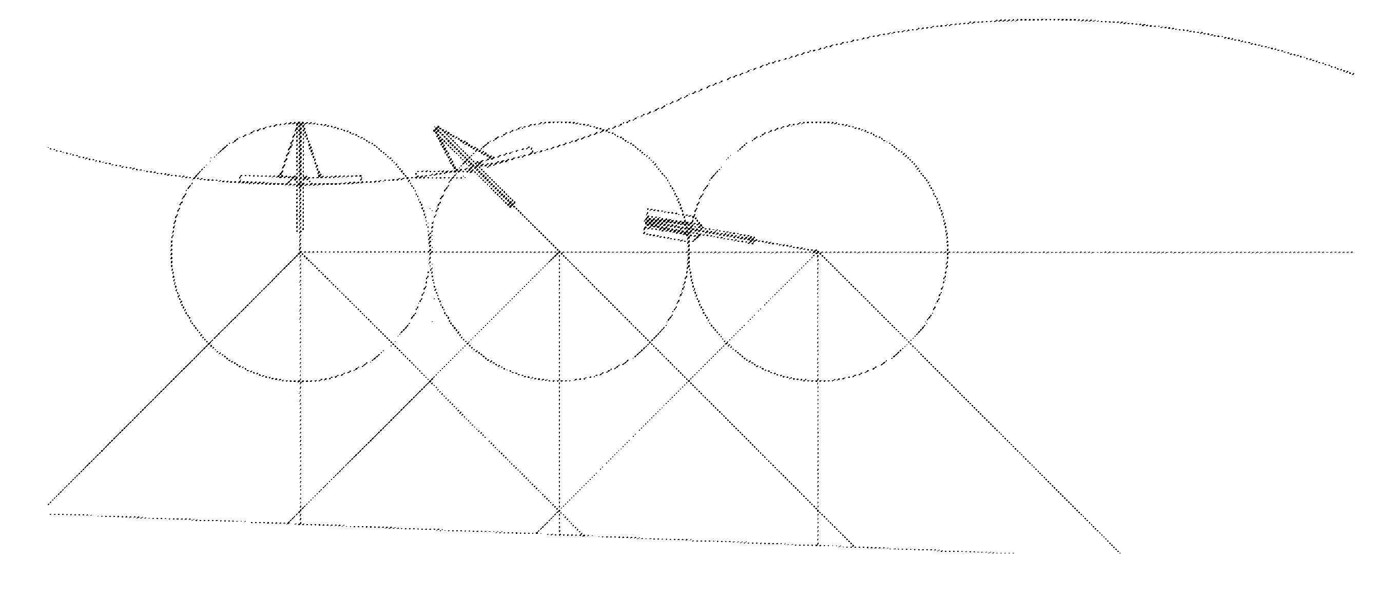
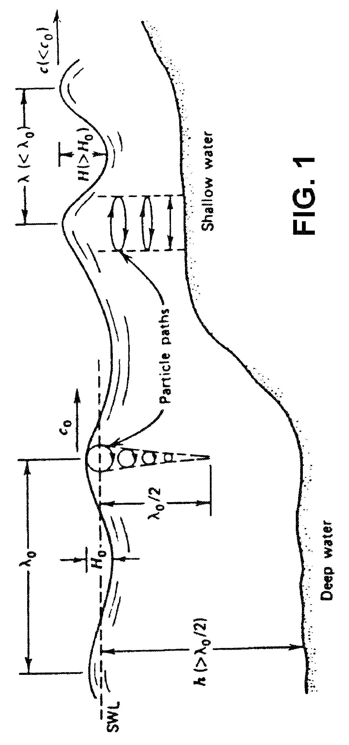
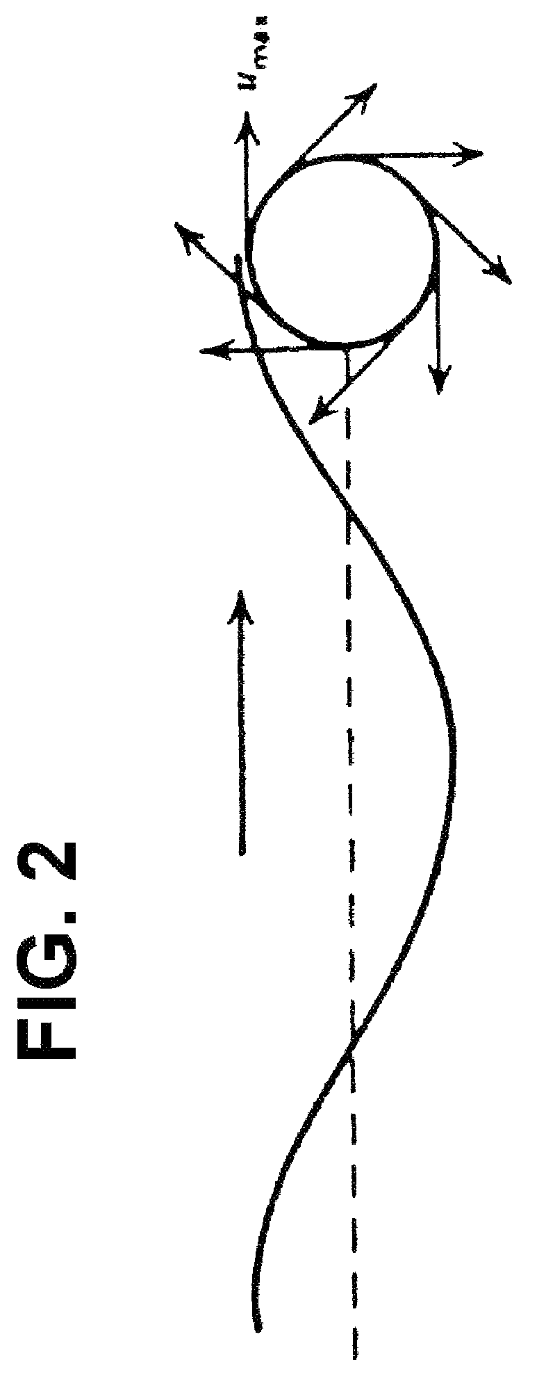
[0021]In order to understand the wave energy apparatus and system of the present invention, we need to explain how waves are created in view of FIGS. 1 and 2. Wind is caused by differences in temperature due to the solar heating of the earth's atmosphere. When this wind skims over the sea, an interaction is caused in which energy is exchanged between the wind and the sea surface. At first, little ripples arise on the surface. Then, the wind that skims along these ripples causes higher air pressure at the front of the wave than at the back. As a result the ripples change into...


PUM


Abstract

A method and system to capture kinetic energy of the sea waves and convert it to electrical power is presented. The hydrodynamic power of the waves is converted to mechanical power after impacting and moving a special panel. The mechanical power is converted into a controlled-cycle hydraulic power to activate a hydraulic motor, which in turn activates an electrical generator. Electrical power is then measured, controlled and distributed to a power grid or end users.

Description

FIELD OF THE INVENTION[0001]The present invention is related to the generation of power and more particularly, to the generation of hydroelectric power by the use of tidal and / or wave action.BACKGROUND OF THE INVENTION[0002]Energy is produced from a variety of sources such as fossil fuels, nuclear energy, solar energy, and water movement. Now a day, fossil fuels and carbon represent the base of energy resources in terms of dependency. However, depletion and pollution are the biggest financial and environmental concerns for society.[0003]The use of tidal and / or wave movement from the sea provides an energy source that is abundant and does not produce waste products that present pollution problems. Wave energy is a viable option since it comes from the wind, the sun, the tides and it's more concentrated that solar energy alone and wind forces combined. Some prior art devices compress air and use it as a driving force. Some pump water directly through waterwheels. Some others store wat...

Claims


Application Information

Patent Timeline
Patent Type & Authority Patents(United States)
IPC IPC(8): F03B13/10F03B13/12H02P9/04
CPCF03B13/1815Y02E10/38Y02E10/30
Inventor NEGRON CRESPO, JORGE
Owner STRATEGIC DESIGN FEDERATION W LLC
Why Eureka
Try Eureka