Linear-in-dB variable gain amplifier using geometric ladder circuit

a ladder circuit and linear amplifier technology, applied in amplifiers, amplifiers with semiconductor devices/discharge tubes, amplifier control details, etc., can solve the problems of requiring significant overhead in unused steps, no regular, rational relationship among the values of resistors in the ladder,

Active Publication Date: 2008-03-04
MARVELL ASIA PTE LTD
View PDF10 Cites 10 Cited by
  • Summary
  • Abstract
  • Description
  • Claims
  • Application Information

AI Technical Summary

Benefits of technology

[0012]Such an arrangement can become inefficiently large, however, as the gain range increases. Therefore, in a second preferred embodiment, multiple amplifier stages are used. In a first stage, a first ladder having a smaller number of relatively large steps, making up the desired range, is provided. In a second stage, a second ladder having a number of smaller steps is provided. Preferably, the size of the larger step is substantially an integral multiple of the size of the smaller step, and the number of smaller steps is selected so that the range of the second stage is substantially equal to the size of one of the larger steps of the first stage. In such an arrangement, the first stage provides coarse tuning of the gain while the second stage provides fine tuning of the gain, generally with a savings in area and numbers of components.
[0014]In the second embodiment, the two stages preferably are connected in such a way that the gains of the two stages, measured in dB, are additive. Thus, selecting zero gain in the first stage allows the second stage to provide 0 dB, 0.5 dB, 1.0 dB, 1.5 dB or 2.0 dB of gain. Selecting 2.5 dB of gain in the first stage allows the second stage to provide 2.5 dB, 3.0 dB, 3.5 dB, 4.0 dB or 4.5 dB of gain. Selecting 5.0 dB of gain in the first stage allows the second stage to provide 5.0 dB, 5.5 dB, 6.0 dB, 6.5 dB or 7.0 dB of gain. Selecting 7.5 dB of gain in the first stage allows the second stage to provide 7.5 dB, 8.0 dB, 8.5 dB, 9.0 dB or 9.5 dB of gain. This is achieved with eleven rungs and nine switches instead of 21 rungs and twenty switches.

Problems solved by technology

However, most electronic devices are now integrated devices that are not inherently logarithmic.
However, there is no regular, rational relationship among the values of the resistors in the ladder.
This approach therefore requires significant overhead in unused steps to obtain enough steps to approximate linear-in-dB behavior.

Method used


Image

  • Linear-in-dB variable gain amplifier using geometric ladder circuit
  • Linear-in-dB variable gain amplifier using geometric ladder circuit
  • Linear-in-dB variable gain amplifier using geometric ladder circuit

Examples


Embodiment Construction

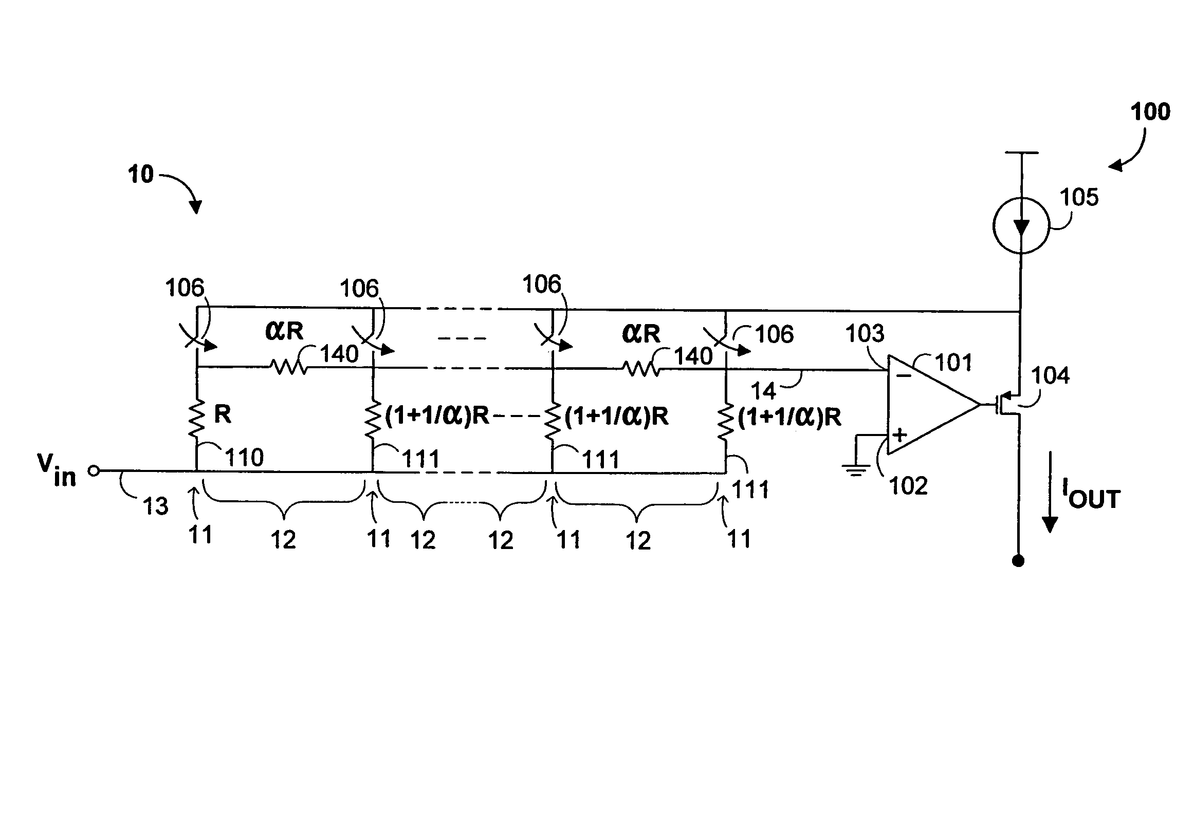
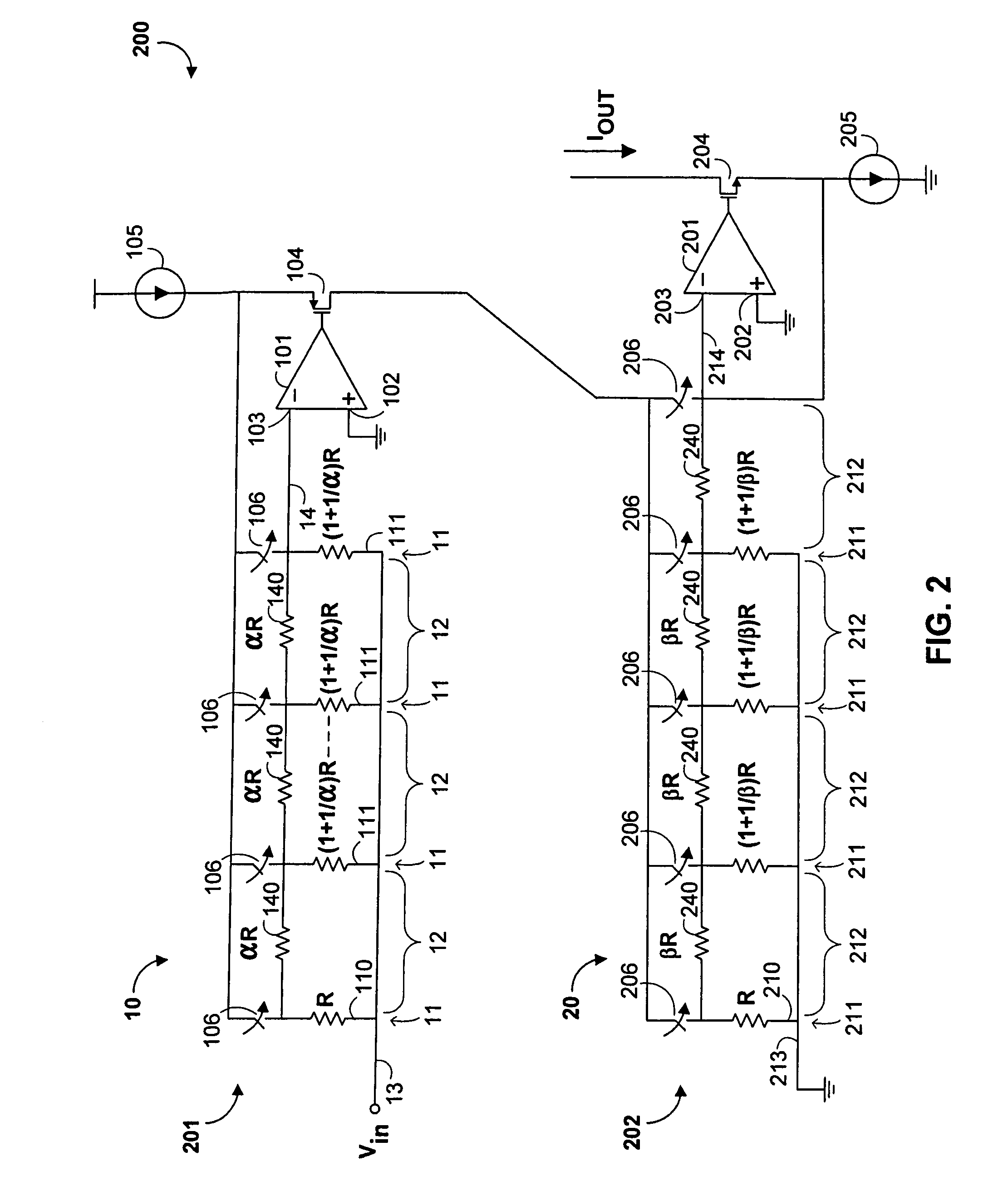
[0027]The invention will now be described with reference to FIGS. 1 and 2. When in the description below of FIGS. 1 and 2, a component is described by the term “resistor,” it should be appreciated that any impedance (with real or complex value, including capacitors or inductors) or other component useful as a resistance can be encompassed by the term “resistor.” For example, in an integrated circuit, transistors may be used as a resistors. In addition, a single resistor may be constructed from a plurality of resistors.

[0028]Thus, a resistance of, e.g., 4Ω can be constructed from a single 4Ω resistor, or from two 2Ω resistors, or from a 3Ω resistor and a 1Ω resistor. Moreover, while the invention may be implemented as a differential amplifier, for ease of illustration it is described below in single-ended form. However, the principles of the invention are the same for the single-ended and differential cases.

[0029]FIG. 1 shows a first preferred embodiment of a variable gain amplifier ...


PUM


Abstract

A variable gain amplifier uses a geometric ladder circuit that produces a transfer function having substantially uniform steps measured in dB. Where the ladder has a plurality of substantially identical resistor rungs of a first resistance, one stile that is a conductor connecting the rungs, and another having a series of substantially identical resistors of a second resistance, then for identical inputs at different rungs, the output signal at an end of the ladder is attenuated by a number of substantially equal steps, one for each rung between input and output. For a ladder with a base rung R, an output at an end opposite the base rung, stile resistors of resistance αR, and other rungs all of resistance (1+(1 / α))R, the step size is 20 log10(1+α). By using such ladders in op-amp feedback loops, chaining different stages with different values of α, coarse and fine gain adjustment can be provided.

Description

CROSS REFERENCE TO RELATED APPLICATION[0001]This claims the benefit of copending, commonly-assigned U.S. Provisional Patent Applications Nos. 60 / 695,289 and 60 / 775,966, filed Jun. 30, 2005 and Feb. 22, 2006, respectively, each of which is hereby incorporated herein by reference in its respective entirety.BACKGROUND OF THE INVENTION[0002]This invention relates to a variable gain amplifier incorporating a resistor ladder circuit with a linear-in-dB transfer function, to provide an output with linear-in-dB gain steps.[0003]In many electronic applications it is necessary or preferred to be able to adjust signal levels in steps that are linear when measured in decibels, or “linear-in-dB.” Because intensity in decibels is a logarithmic function, this means that circuits that act logarithmically, or can mimic logarithmic activity, are desirable.[0004]Bipolar transistors, by the exponential nature of the physics of their operation, are inherently logarithmic in operation. However, most elec...

Claims


Application Information

Patent Timeline
Patent Type & Authority Patents(United States)
IPC IPC(8): H03G3/12
CPCH03G1/0088H03G7/005
Inventor SHIRVANI-MAHDAVI, ALIREZACHIEN, GEORGE
Owner MARVELL ASIA PTE LTD
Why Eureka
Try Eureka