Signal transmitter and signal receiver
a signal transmitter and receiver technology, applied in the field of signal transmission apparatus and signal reception apparatus, can solve the problems of frequent errors, complicated cable connection between the signal transmission apparatus and the signal reception apparatus, etc., and achieve the effect of removing noise at display
- Summary
- Abstract
- Description
- Claims
- Application Information
AI Technical Summary
Benefits of technology
Problems solved by technology
Method used
Image

Examples
embodiment 1
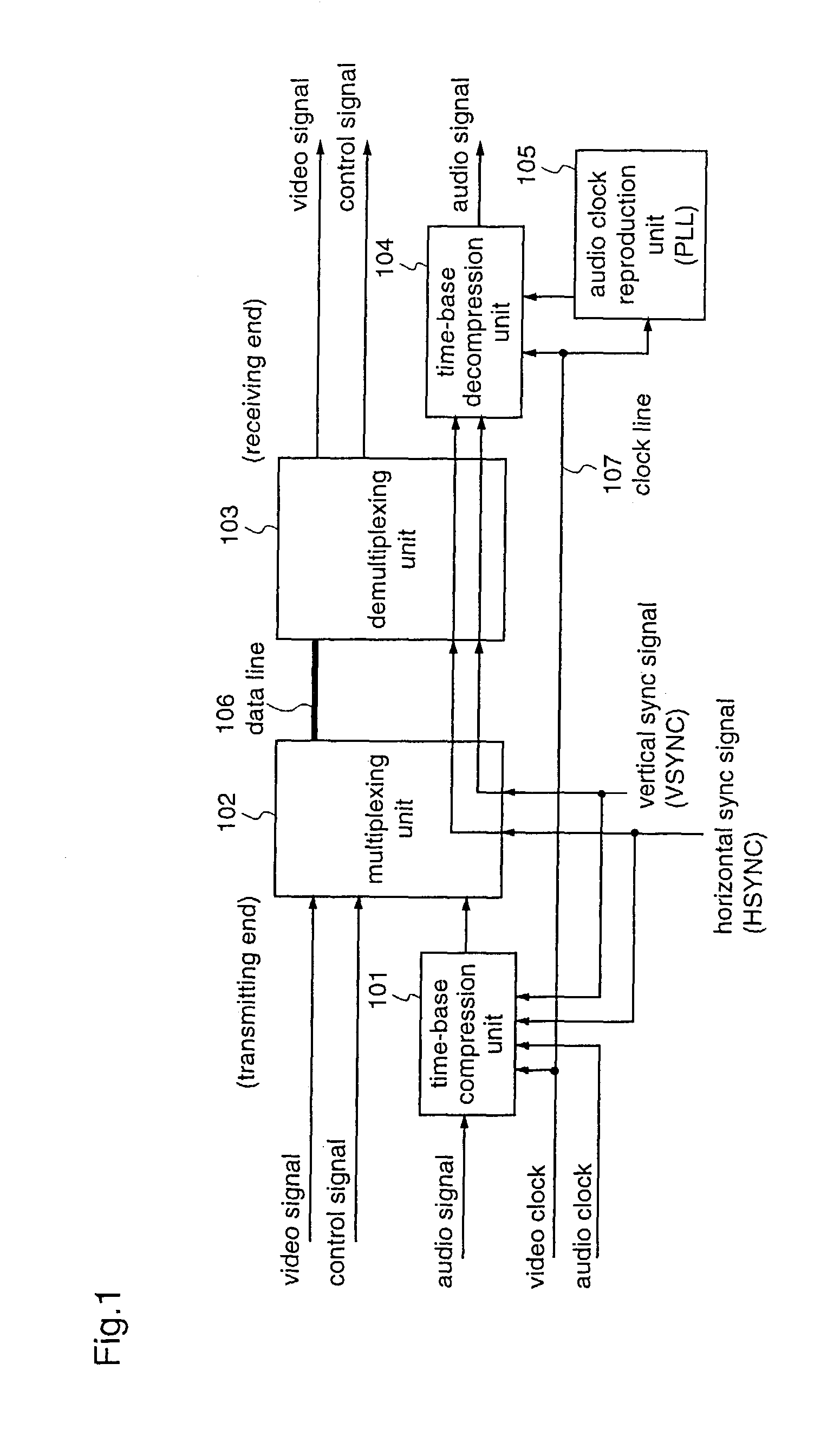
[0080]FIG. 1 is a diagram illustrating the construction of a signal transmission system according to a first embodiment.
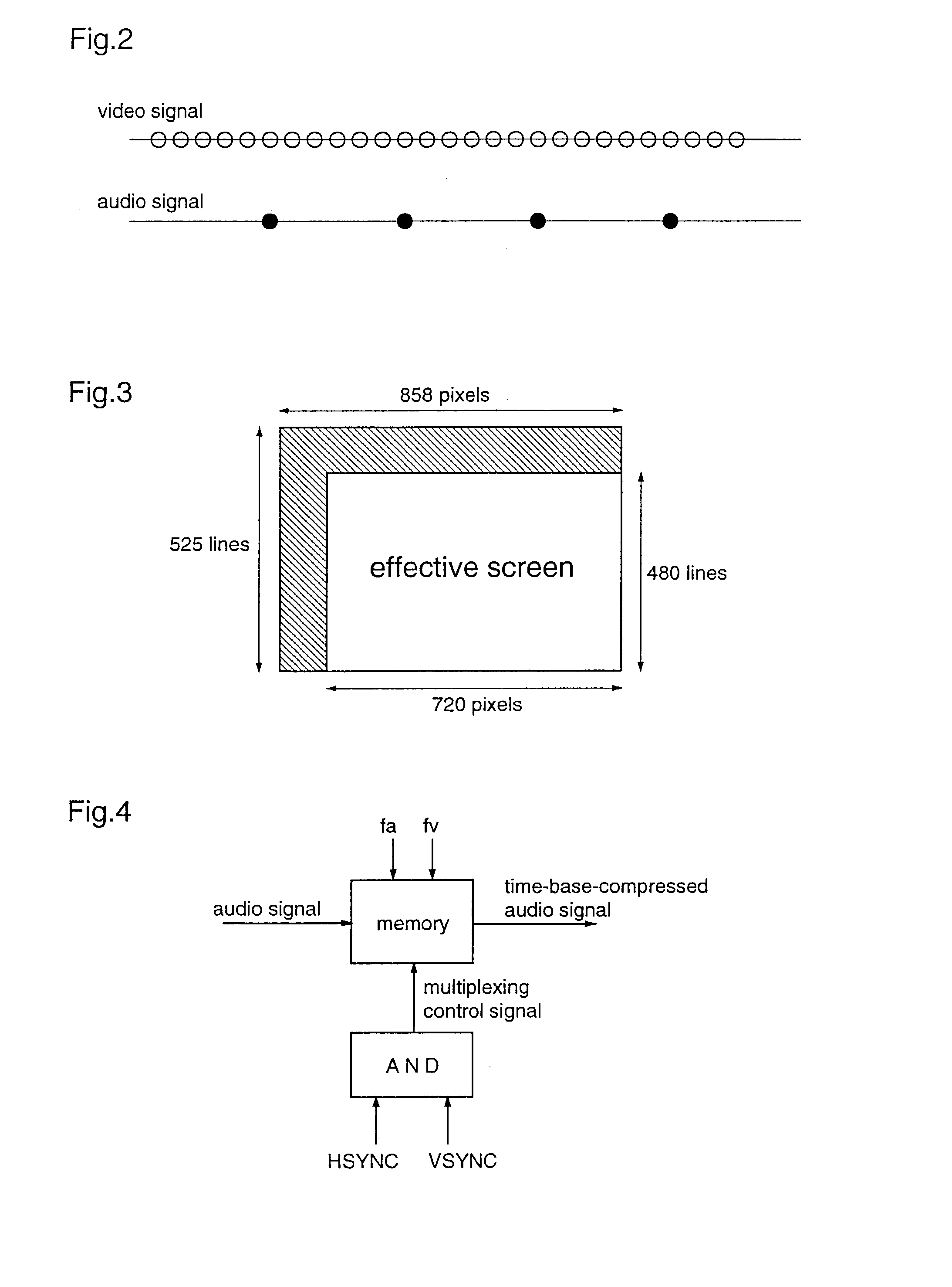
[0081]With reference to FIG. 1, numeral 101 denotes a time-base compression unit for compressing an audio signal on the time axis. The internal construction of the time-base compression unit 101 is shown in FIG. 4. In FIG. 4, the time-base compression unit 101 is constituted mainly by a memory, and converts the rate of the inputted audio signal. To be specific, a sampling clock for input is an audio clock “fa”, and a sampling clock for output is a video clock “fv”. Here, “fa” is an audio sampling clock frequency, and “fv” is a video sampling clock frequency. A multiplexing control signal is used for controlling the output of the [time compression unit] time base compression unit 101. This multiplexing control signal is the AND of a horizontal sync signal and a vertical sync signal. The horizontal sync signal and the vertical sync signal are negative logic.
[0082]Num...
embodiment 2
[0104]Hereinafter, a signal transmission system according to a second embodiment will be described with reference to the FIGS. 14 to 17. According to this second embodiment, the signal transmission system according to the first embodiment is applied to the DVI (Digital Visual Interface) standard.
[0105]FIG. 14 is a diagram illustrating the construction of the signal transmission system according to the second embodiment.
[0106]In FIG. 14, numeral 301 denotes a time-base compression unit. This is identical to the time-base compression unit 101 employed in the first embodiment, and thus a description thereof will be omitted here.
[0107]Numeral 302 denotes a decomposition unit for decomposing a time-base-compressed audio signal to superimpose on signals in CTL1, CTL2, and CTL3 based on the DVI standard. The decompression unit 302 includes a control signal superimposing means for superimposing the control signal on the audio signal.
[0108]The control signal superimposing means will be descr...
embodiment 3
[0134]Hereinafter, a signal transmission system according to a third embodiment will be described. According to this third embodiment, in the signal transmission system described in the first embodiment, the signal transmission apparatus transmits a signal which has been transmitted at 24P of cinema or a signal imaged at 30P, to the signal reception apparatus. Generally, in a television video signal of cinema, video of the same frame (screen) is transmitted at a cycle of two times / three times. This is because the television video signal is operated at 60 Hz (locally 50 Hz) as compared with cinema being operated at 24 Hz (24-frame / second).
[0135]FIG. 20 shows an example of a television signal in which a picture of cinema is transmitted at 60 Hz at the cycle of two times / three times.
[0136]In FIG. 20, a control signal 1 and a control signal 2 are outputted from an MPEG decoder, and superimposed on a blanking period together with an audio signal, and the superimposed signal is digitally ...
PUM
 Abstract
Description
Claims
Application Information
 - R&D
- Intellectual Property
- Life Sciences
- Materials
- Tech Scout
- Unparalleled Data Quality
- Higher Quality Content
- 60% Fewer Hallucinations
Browse by: Latest US Patents, China's latest patents, Technical Efficacy Thesaurus, Application Domain, Technology Topic, Popular Technical Reports.
© 2025 PatSnap. All rights reserved.Legal|Privacy policy|Modern Slavery Act Transparency Statement|Sitemap|About US| Contact US: help@patsnap.com