Optical sensor and system

Inactive Publication Date: 2008-03-04
MCMASTER UNIV
View PDF4 Cites 20 Cited by
  • Summary
  • Abstract
  • Description
  • Claims
  • Application Information

AI Technical Summary

Benefits of technology

[0010]Some embodiments of the invention provide an optical sensor having a core, at least one cladding layer, at least one high refractive index over-layer and at least one sensing layer. The high refractive index over-layer acts as a sensitivity enhancement layer, with a refractive index larger than that of the cladding layers. A periodic structure such as a long-period grating (LPG) is formed in the co

Problems solved by technology

This results in a change in reflection and/or transmission spectrum of the periodically modulated fiber.
Enhancing sensitivity is a key issue in the development of optical sensors and is especially important when the change in the ambient environment or in volume (e.g. size and concentration) of analyte is small.
Despite the successful demonstration of high sensitivity SPR sensors based on bulk and planar waveguide devices, high performance fiber-optic SPR sensors have not been reported mainly due to difficulties in device fabrication and operation.
It is difficult to deposit a homogeneous coating and achieve good

Method used


Image

  • Optical sensor and system
  • Optical sensor and system
  • Optical sensor and system

Examples


Embodiment Construction

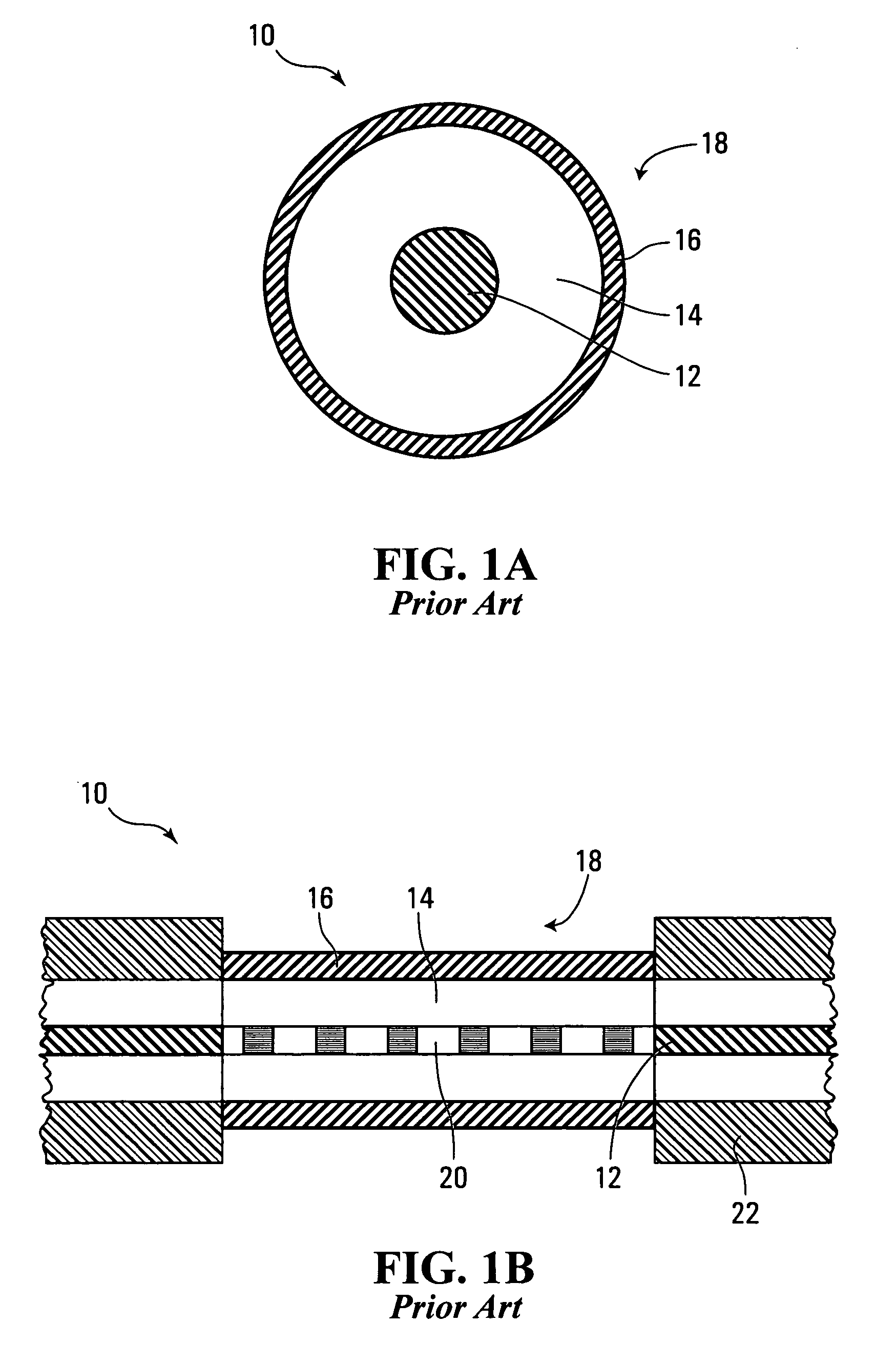
[0039]Referring to FIGS. 1A and 1B, shown are transverse and longitudinal cross sections, respectively, of a conventional optical fiber biosensor 10. Biosensor 10 has a core 12, a cladding 14, and a sensing layer 16. Optical fiber biosensor 10 is essentially two concentric cylinders, the inner cylinder being core 12 and the outer cylinder cladding 14, with sensing layer 16 being deposited on the exterior of cladding 14. Core 12 has a long-period grating 20. Sensing layer 16 is exposed to an ambient environment 18. A jacket 22 surrounds biosensor 10 at both ends of the device.

[0040]Various optical sensors in accordance with embodiments of the invention will now be described.

Four-Layer Structure

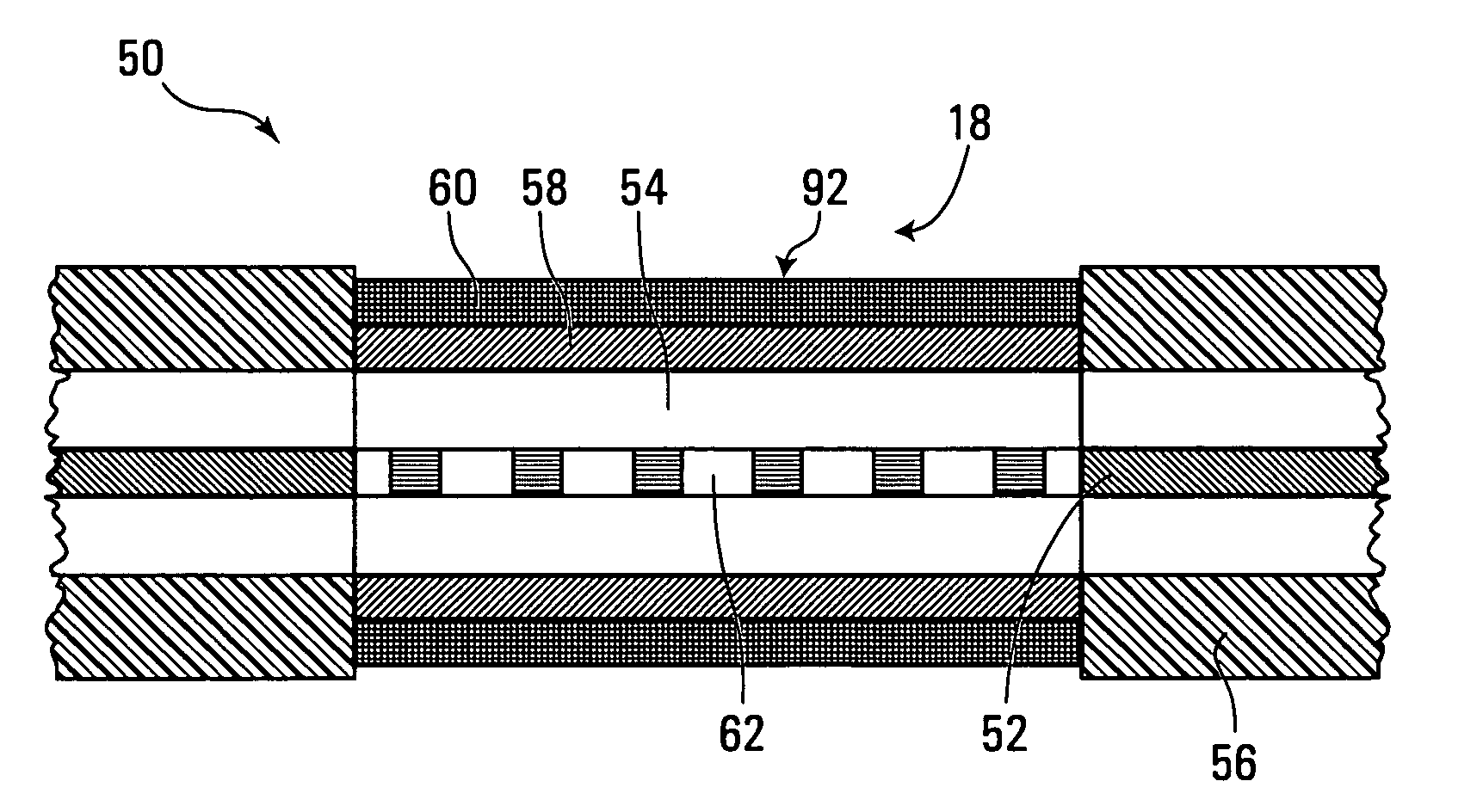
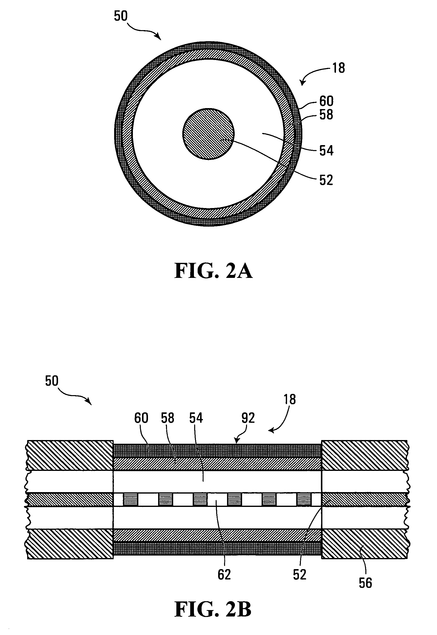
[0041]Referring to FIGS. 2A and 2B, shown are transverse and longitudinal cross sections, respectively, of an optical sensor in the form of a four-layer structure of a sensitivity enhanced biosensor 50, according to an embodiment of the invention. The structure is formed on an optical fiber hav...


PUM


Abstract

An optical sensor has a core, a cladding, and an over-layer. In some embodiments the optical sensor also has a sensing layer. The over-layer acts as a sensitivity enhancement layer, with a refractive index larger than that of the cladding layers. A periodic structure, such as a long-period grating (LPG), is formed in the core. A transmission spectrum of the device shows several notches due to the existence of the LPG. A change in the sensing layer's refractive index and/or thickness results in a shift in the notch wavelengths of the LPG. By choosing proper refractive indices and thicknesses of the core, the cladding and the over-layer, the shift in the notch wavelengths can be significantly enhanced.

Description

CROSS-REFERENCE TO RELATED APPLICATIONS[0001]This application claims the benefit of U.S. Provisional Application No. 60 / 672,847 filed Apr. 20, 2005 which is hereby incorporated by reference.FIELD OF THE INVENTION[0002]The invention relates to optical sensors which have applications in the fields of medicine and biomedicine.BACKGROUND OF THE INVENTION[0003]Optical sensors are devices that can be used to detect the change in an ambient environment and / or existence of analytes in the ambient environment. For example, if the sensor is formed with a biologically derived binding agent that has selective chemical or biological interaction with a certain analyte, a biosensor can be formed. Biosensors have attracted considerable attention recently due to their potential applications in medical diagnostics, explosives detection, determination of food quality, genetic screening and environmental monitoring.[0004]To date, many optical sensors have been proposed and demonstrated. Long-period gra...

Claims


Application Information

Patent Timeline
IPC IPC(8): G02B6/00
CPCG01N21/774G02B6/02104
Inventor XU, CHANG-QINGYANG, JIAN
Owner MCMASTER UNIV
Why Eureka
Try Eureka