
Solar power generation system

a solar power generation and solar energy technology, applied in the direction of heat collector mounting/support, lighting and heating equipment, greenhouse gas reduction, etc., can solve the problems of limited success, large impact of solar energy on the earth's surface, and the pursuit of harnessing this energy, so as to achieve less efficiencies, less expensive components, and low cost

Inactive Publication Date: 2008-03-11
SOLAR ENERGY PRODN CORP
View PDF30 Cites 117 Cited by
  • Summary
  • Abstract
  • Description
  • Claims
  • Application Information

AI Technical Summary

Benefits of technology

[0009]Therefore, there is a need for economically viable approaches to producing electricity by collecting solar energy. The approaches described herein meet that need by including low cost, stock components and devices rather than custom components and devices that incorporate exotic materials. These approaches recognize that an economically viable system can be achieved with lesser efficiencies but with less expensive components.

Problems solved by technology

However, for many terrestrial locations, a great deal of solar energy impinges on the earth's surface every day.
Some efforts to harness this energy have been pursued, but with limited success.
Though simple and clean, even after years of development, PV devices remain quite expensive and cost prohibitive, resulting in long pay back periods.
Also, PV devices produce relatively low voltage direct current (DC), which has generally limited PV devices to local use incompatible with using PV devices to support the grid.
Such efforts have required complex devices, such as focusing concentrating mirrors to heat oil to very high temperatures.
Although a few operating plants have been built, the cost of designing and building these plants is very high.
Thus, these plants are not remotely economical and there is little, if any, return of investment.
Because the economics do not justify these plants and because very few geographic locations are suitable, no economies of scale are available to make these plants more viable.
These and other factors make traditional solar thermal plants economically unviable.

Method used


Image

  • Solar power generation system
  • Solar power generation system
  • Solar power generation system

Examples


Embodiment Construction

[0043]As discussed further below, the embodiments described are advantageously configured to be constructed mainly of stock components and thus at comparatively low cost so that electrical power is produced in an economically viable manner. The systems are environmentally friendly in that they convert a renewable resource, e.g., solar energy flux from the sun, into electrical power. This application discusses a variety of electrical power generation systems.

I. Systems Configured to Generating Electrical Power Ecnomically from Solar Energy Flux

[0044]The systems described below operate by heating a working fluid solely with solar energy flux and by one or more additional heat sources, some of which can be non-renewable.

A. Direct Heating of a Working Fluid with Solar Energy Flux

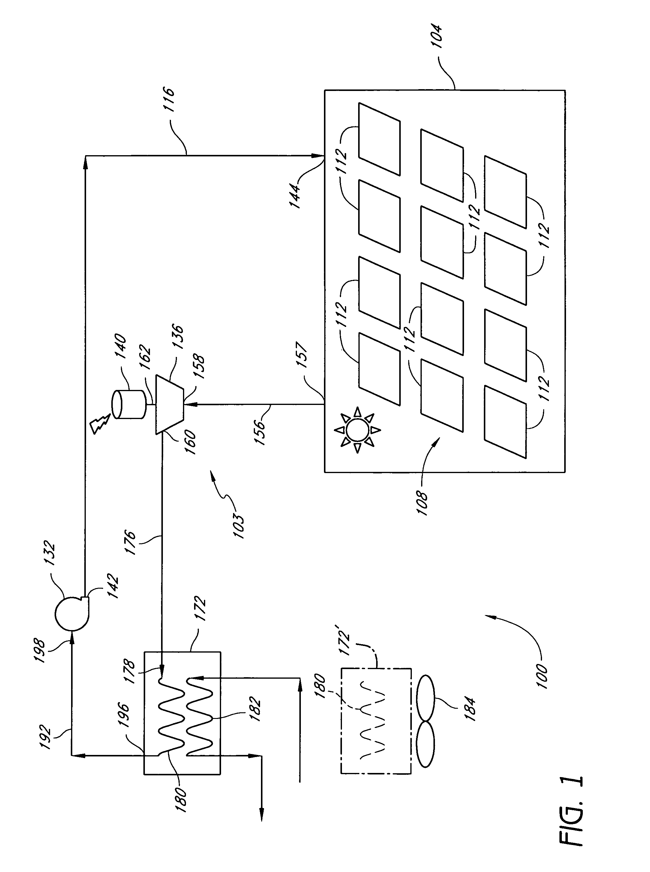
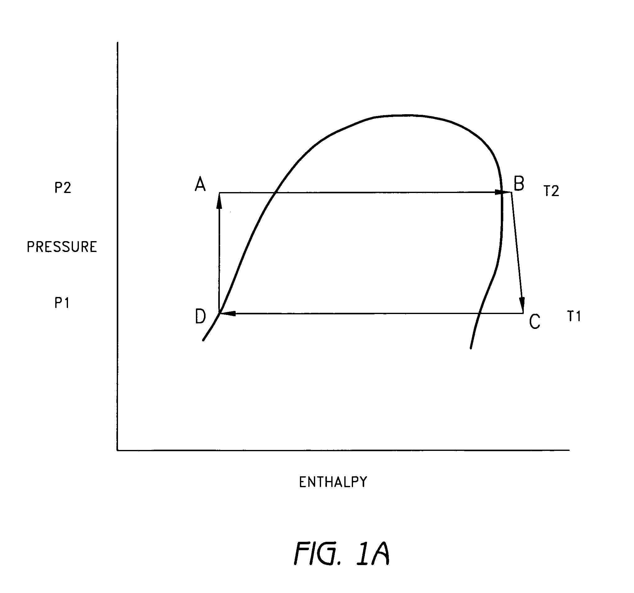
[0045]FIG. 1 schematically illustrates one embodiment of an economical solar generator system 100. As discussed further below, the solar generator system 100 can operate on a suitable thermodynamic cycle. The sy...


PUM


Abstract

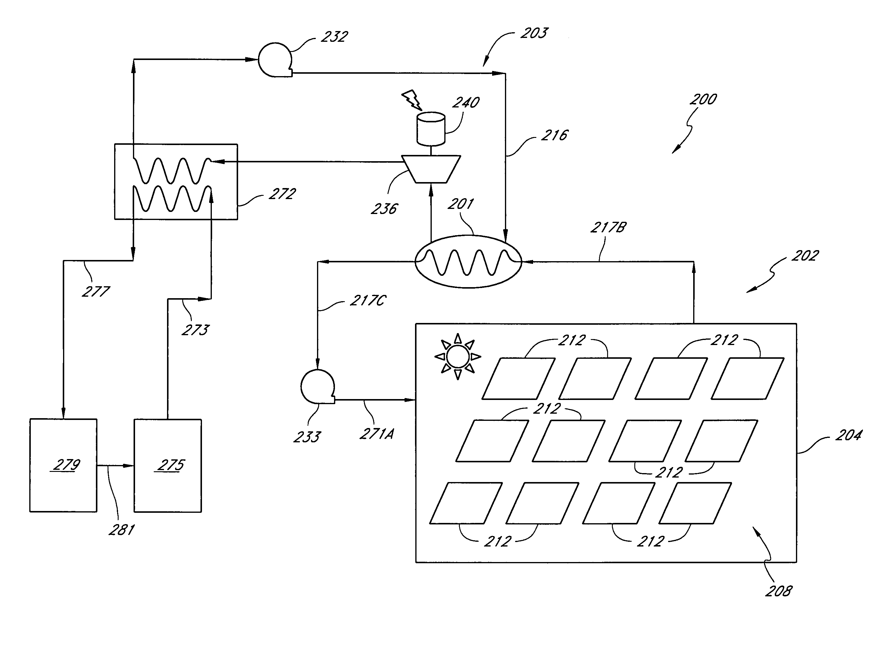
An economical solar generator system is provided wherein the solar energy collector is constructed from a plurality of heat exchangers of the kind used as evaporators in automobile air conditioners. The solar generator system includes a plurality of said heat exchangers connected to receive incoming liquefied refrigerant under pressure. The number of such heat exchangers is sufficient to collect solar energy sufficient to induce a phase change from a liquid to a gas state. The solar generator system also includes an air motor and an electric generator. The air motor is coupled to the outflow heated gas from the plurality of heat exchangers. The air motor is rotated by the heated gas. The electrical generator is coupled to the air motor so that rotation of said air motor causes rotation of said generator.

Description

CROSS-REFERENCE TO RELATED APPLICATIONS[0001]This application claims the benefit of U.S. Provisional Application No. 60 / 522,660, filed Oct. 26, 2004.BACKGROUND OF THE INVENTION[0002]1. Field of the Invention[0003]This application is directed to economical solar generator systems.[0004]2. Description of the Related Art[0005]There is an enormous amount of solar energy provided by the sun that is available without significant environmental impact, or “green”. This energy is essentially free, in that it continually falls on the surface of the earth. The amount of energy impinging at any particular locale is a function of the geographic location, adverse atmospheric conditions, and season change. However, for many terrestrial locations, a great deal of solar energy impinges on the earth's surface every day. Unlike other sources of energy, solar energy does not require exploration, extraction of materials or refining.[0006]Some efforts to harness this energy have been pursued, but with li...

Claims


Application Information

Patent Timeline
IPC IPC(8): B60R16/00
CPCF03G6/003F24J2/24F24J2/26F24J2/42F24J2/50F24J2/5233F28B1/02F28D20/0043F28D2020/006Y02E10/44Y02E10/46Y02E10/47Y02E60/142Y02E70/30F24S10/70F24S10/75F24S25/13F24S80/50F24S90/00Y02E60/14
Inventor RUBAK, JEFFREYYAMBRACH, MICHAEL
Owner SOLAR ENERGY PRODN CORP
Learn More