System using power converter, microsurge suppressor and microsurge suppression method

a technology of power converter and micro-surge, which is applied in the direction of emergency protective arrangements for limiting excess voltage/current, printed circuit non-printed electric components association, electrical apparatus casing/cabinet/drawer, etc., and can solve problems such as deterioration of equipment forming a system, affecting reliability and life, and causing the current flowing on the side of the shaft of the motor

Inactive Publication Date: 2008-03-11
KEIO UNIV
View PDF4 Cites 3 Cited by
  • Summary
  • Abstract
  • Description
  • Claims
  • Application Information

AI Technical Summary

Benefits of technology

[0017]The invention is made in view of the above-mentioned situation and the object is to suppress a surge generated at the terminal of equipment connected to a power converter without depending upon a condition of a component such as the length of a cable and the capacity of the power converter and to simultaneously suppress radiation noise and current (shaft current) that flows on its shaft in case a load is a motor.

Problems solved by technology

When the microsurge is caused, the insulation of equipment forming a system is deteriorated, and the reliability and the life are deteriorated.
Besides, in case common mode current via the stray capacitor of the equipment is caused because of surge voltage and a load is a motor, shaft current that flows on the side of the shaft of the motor is caused.
Further, as strong radiation noise is caused in the vicinity of the power supply terminal of the load, electromagnetic interference is caused in near electronic equipment and a near information communication device.
Particularly, as most objects that utilize a recent power converter use information equipment, the effect is serious.
Besides, the effect upon wireless LAN being popularized and networked home by wireless to be expected in future is also serious.
However, as the proper performance of the power converter may be deteriorated by the addition of these means for the measures, countermeasures in which wavelike effect upon the whole system including the power converter is fully examined are required.
Besides, as countermeasures in which the characteristics of the cables and the input impedance and others of the motor and others are fully grasped are required, measurement requiring labor and intricate computing are required and improvement is required in terms of flexibility.
Further, when anew component is added for a measure against a microsurge, the induction of common mode current from the component and the generation of radiation noise cannot be avoided.
Besides, when the capacity of the power converter is increased, the large-sizing of the component for a countermeasure which is made of iron and which includes winding structure and the increase of the weight cannot be avoided and the cost is increased.

Method used


Image

  • System using power converter, microsurge suppressor and microsurge suppression method
  • System using power converter, microsurge suppressor and microsurge suppression method
  • System using power converter, microsurge suppressor and microsurge suppression method

Examples


Embodiment Construction

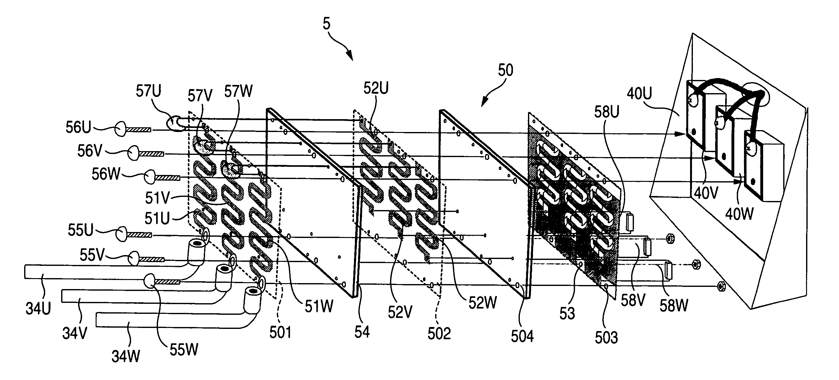
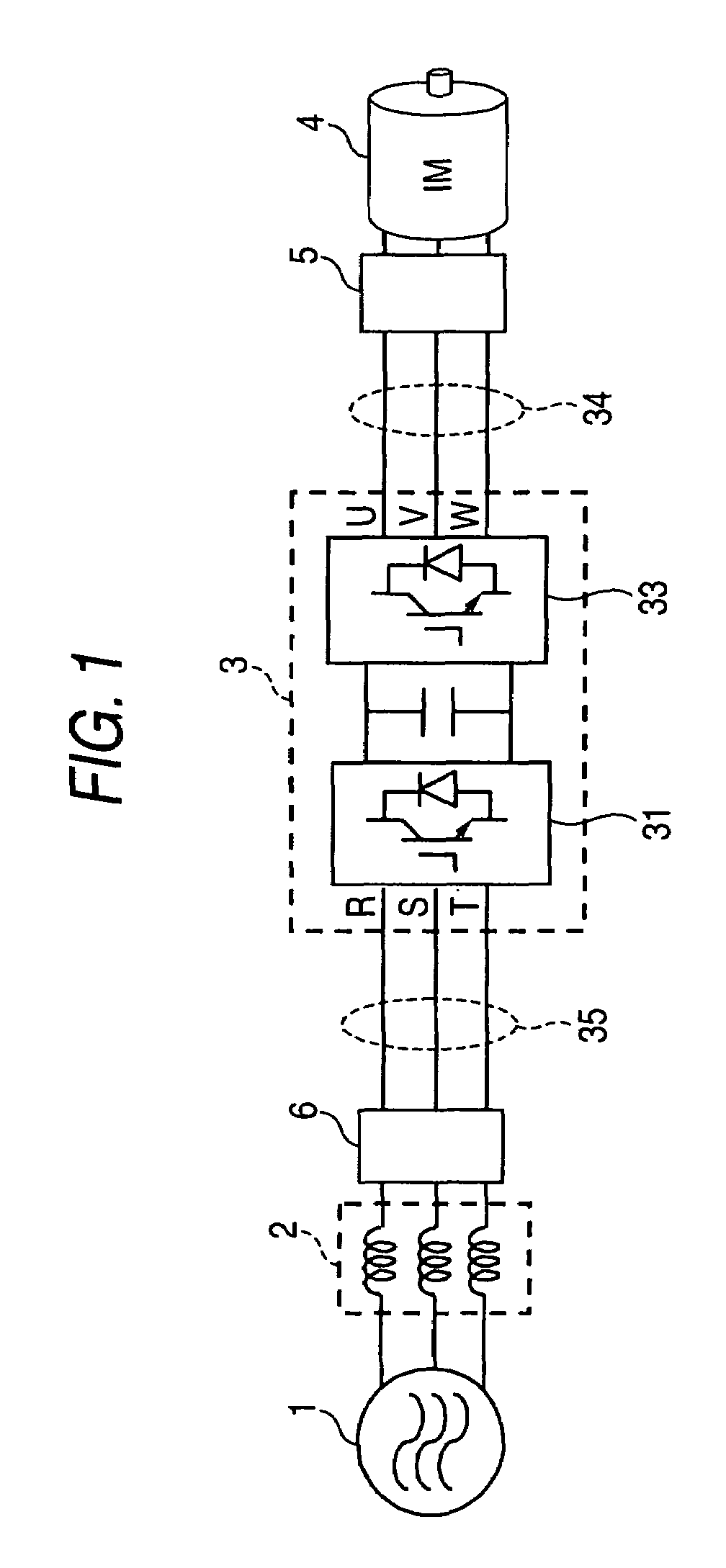
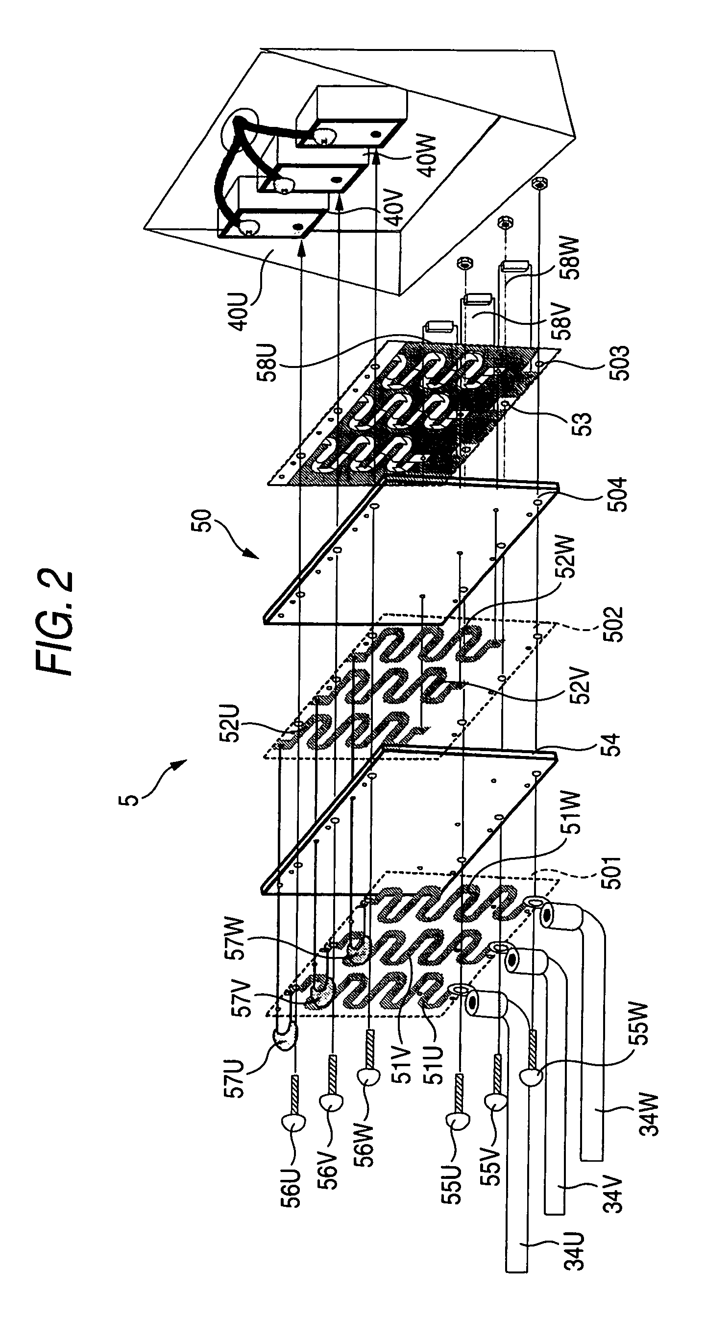
[0051]Referring to the drawings, embodiments of the invention will be described below. FIG. 1 shows a motor driving system using a power converter controlled by switching, and an AC power supply 1, an AC reactor 2, the power converter 3 and a motor 4 are the same as those in the system shown in FIG. 11. The motor driving system according to the invention is different from the system shown in FIG. 11 in that a microsurge suppressor 5 is inserted on a power supply line from the power converter 3 to the motor 4 and the similar microsurge suppressor 6 is inserted on a power supply line from the AC reactor 2 to the power converter 3. However, the microsurge suppressor 6 is not essential and can be omitted. As shown in FIGS. 12 and 13, as surge voltage at the terminal of the AC reactor 2 is smaller than surge voltage at the terminal of the motor 4 and further, the length of a cable can be also shortened, the microsurge suppressor 6 may be also omitted depending upon the magnitude of the s...


PUM


Abstract

A motor driving system includes an AC power supply 1, an AC reactor 2, a power converter 3 and a motor 4. A microsurge suppressor 5 is inserted on a power supply line from the power converter 3 to the motor 4 and the similar microsurge suppressor 6 is inserted on a power supply line from the AC reactor 2 to the power converter 3. The microsurge suppressor 5 includes a multi-layer printed wiring board having two terminals connected to the power converter 3 and the motor 4 and a capacitor for bypassing a surge, and the terminal 4 on the side of the motor of the multi-layer printed wiring board is directly connected to a terminal of the motor 4. The capacitor for bypassing a surge is connected between the terminal of the motor 4 and the end on the side of a second terminal of second wiring.

Description

BACKGROUND OF THE INVENTION[0001]The present invention relates to a system using a power converter controlled by switching, for example, a system that drives various loads such as a motor by the output of a power converter.[0002]A power converter controlled by switching is used for driving various equipment such as a motor and is also utilized in fields of household electrical appliances, transportation equipment, an uninterruptible power system, a solar generator and a fuel cell. To realize required performance, the improvement of the switching characteristics of power elements forming the power converter is required to be promoted, switching speed for pulse width control is 10 to 100 ns and is considerably fast.[0003]When pulse voltage having an abrupt waveform and generated because of high speed PWM (Pulse Width Modulation) control is applied to equipment connected to the power converter, for example, an AC reactor connected to the side of a converter (the side of an alternating-...

Claims


Application Information

Patent Timeline
Patent Type & Authority Patents(United States)
IPC IPC(8): H05K5/00H02H9/04H02H9/06H02M1/12H02M1/14H02M7/00
CPCH02M1/32H02M7/003
Inventor MUTOH, NOBUYOSHI
Owner KEIO UNIV
Why Eureka
Try Eureka