
Operation recognition system enabling operator to give instruction without device operation

Inactive Publication Date: 2008-03-11
TOSHIBA MEDICAL SYST CORP
View PDF9 Cites 46 Cited by
  • Summary
  • Abstract
  • Description
  • Claims
  • Application Information

AI Technical Summary

Benefits of technology

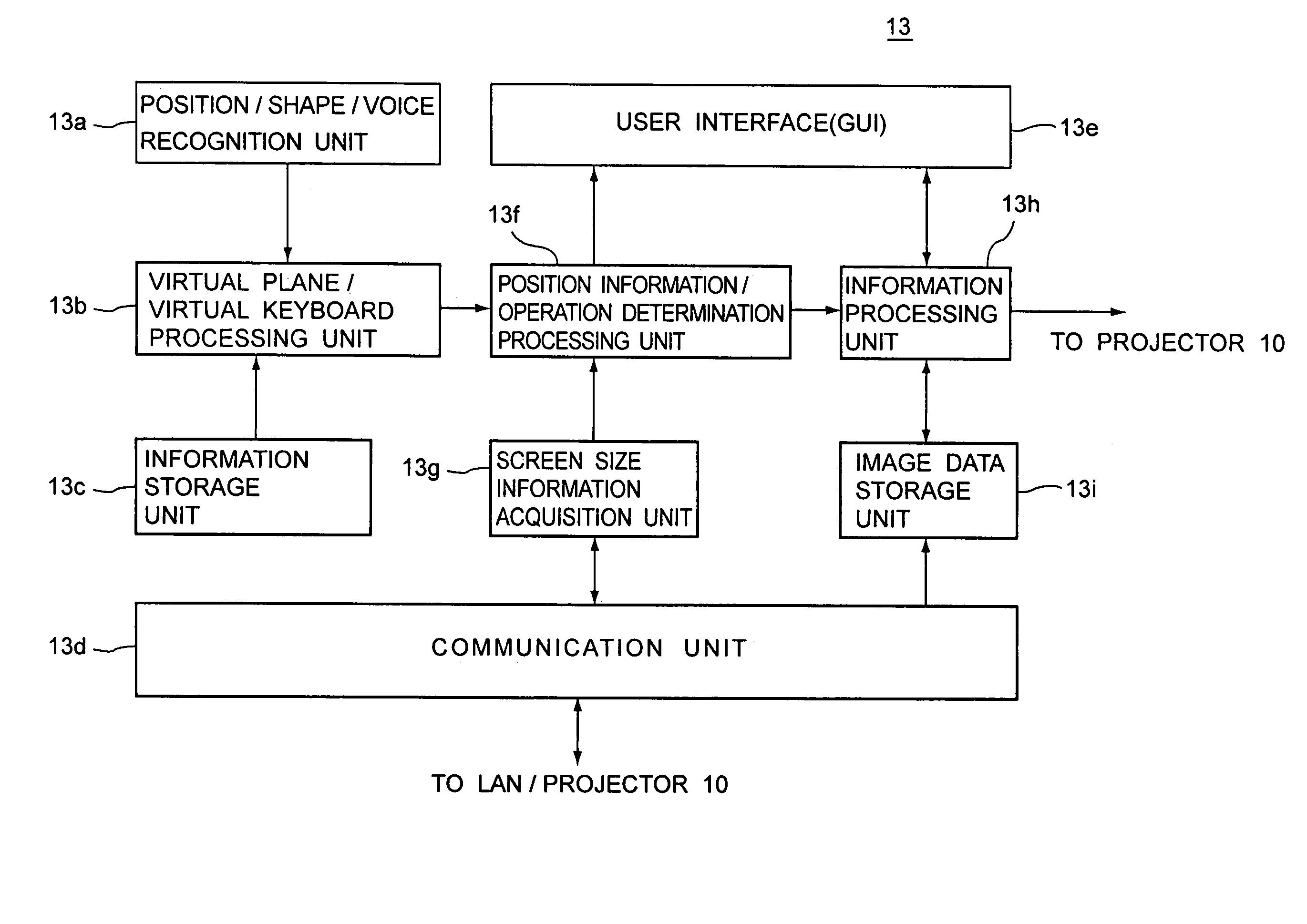
[0010]According to a first aspect of the present invention, there is provided an operation recognition system. The system includes an object to be operated, at least one camera, a processor, and a controller. The at least one camera is configured to acquire image data of an operator. At least the predetermined number of image data is acquired in a predetermined time period. The p

Problems solved by technology

Such a handover is inconvenient for the operators and restricts their operations.
Further, in case of a surgery or an operative treatment, a doctor is not allowed to touch and operate the keyboard or the like during the surgery or the operative treatment from a hygienic point of view.
Such a hand pointing device, however, does not enable the operator to perform the following operations which are usually implemented in a conventional image viewer.

Method used


Image

  • Operation recognition system enabling operator to give instruction without device operation
  • Operation recognition system enabling operator to give instruction without device operation
  • Operation recognition system enabling operator to give instruction without device operation

Examples


first embodiment

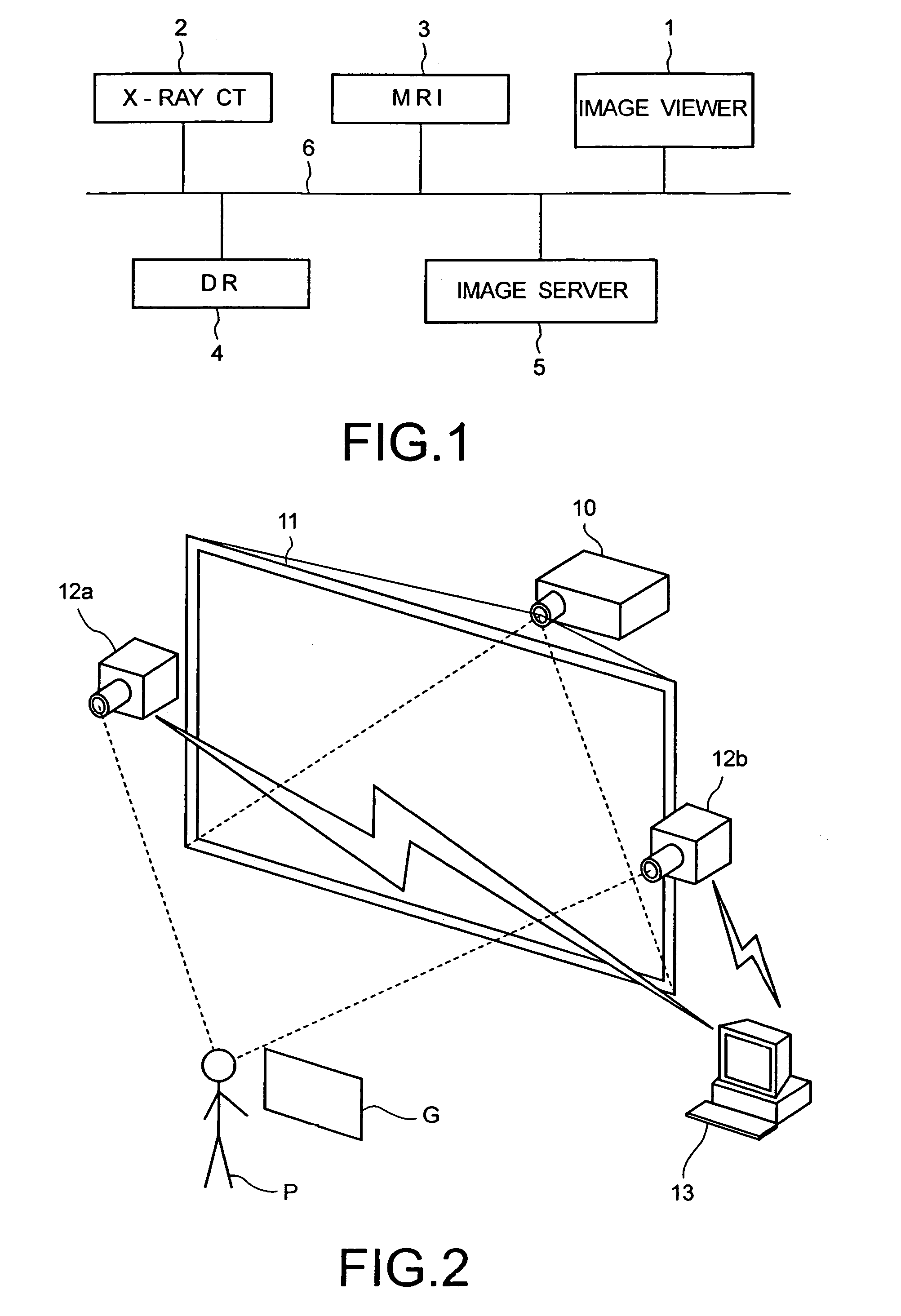
[0033]FIG. 1 is a block diagram showing an exemplary medical image display system according to a first embodiment of the present invention. As shown in FIG. 1, the medical image display system includes an image viewer 1, an X-ray computed tomography apparatus 2, a magnetic resonance imaging apparatus 3, a digital radiography apparatus 4, and an image server 5.

[0034]The image viewer 1 includes a display for displaying-images and an input unit for inputting information or instructions. The display may also be used to display medical examination reports based on medical image interpretations. The input unit includes a keyboard, a mouse, and / or an operation panel. The X-ray computed tomography apparatus 2, the magnetic resonance imaging apparatus 3, and the digital radiography apparatus 4 acquire medical images, respectively. The digital radiography apparatus 4 is used in combination with an X-RAY fluoroscopy (not shown in FIG. 1) and digitally processes X-ray images. The acquired medic...

second embodiment

[0094]A second embodiment of the present invention will regard of an X-ray fluoroscopy position change during a catheter operation as another example of the use of a virtual plane. FIG. 15 is an illustration showing an example of such a fluoroscopy position change through a virtual plane according to the second embodiment of the present invention.

[0095]FIG. 15(a) shows that a doctor S is inserting a catheter into a patient T from the inguina 151. The patient T is lying on a bed 152 which is a part of an X-ray diagnosis apparatus. During the catheter insertion, the X-ray diagnosis apparatus acquires fluoroscopic image data of the patient T. The fluoroscopy is implemented over a body part of the patient T where a head of the catheter is located. Fluoroscopic images based on the acquired image data are displayed by a display monitor 153 so that the doctor S can make visually verify through the display monitor 153 that the insertion is correctly being performed. The display monitor 153 ...

third embodiment

[0106]Operations through a virtual plane are also applied to other fields in everyday life. The virtual plane could be used to control any appliances that normally require physical manipulation to operate. Examples of such appliances might include, but not limited to: lighting fixtures, windows, heating systems, doors, stoves, and various other items capable of being controlled. A third embodiment of the present invention will regard of switching on / off of a fluorescent light fixed to a ceiling as one example. FIG. 16 is an illustration showing an example of such a switching through a virtual plane according to the third embodiment of the present invention.

[0107]As shown in FIG. 16(a), a user V is lying on a bed 161. In a room where the user V is lying, a fluorescent light 162 is fixed to a ceiling of the room. Similar to the first embodiment, there are provided video cameras 163a and 163b at both sides of the fluorescent light 162. The video cameras 163a and 163b acquire image data...


PUM


Abstract

An operation recognition system including an object to be operated, at least one camera, a processor, and a controller. At least one camera is configured to acquire image data of an operator in a predetermined period of time, and a processor is configured to perform recognition processing on the acquired image data. Upon processing the image data, the processor is configured to define a virtual plane in between the object to be operated and the operator. The processor is configured to then perform a process to determine if a predetermined part of the operator penetrates the virtual plane based on the recognition processing. Based on this determination, the controller is configured to control the object to be operated.

Description

CROSS-REFERENCE TO RELATED APPLICATION[0001]This application is based upon and claims the benefit of priority from prior Japanese Patent Application No. P2003-45554, filed on Feb. 24, 2003, the entire contents of which are incorporated herein by reference.BACKGROUND OF THE INVENTION[0002]1. Field of the Invention[0003]The present invention relates to an operation recognition system which recognizes a user's operation without a device and controls an object based on the recognition.[0004]2. Discussion of the Background[0005]In the medical field, an image display apparatus is used to support image interpretation, medical examinations, and explanation to patients, for example, through a graphical user interface (GUI). Such an image display apparatus is known as a workstation or an image viewer and is described, for example, in Japanese Patent Application Publication No. PH5-12352.[0006]In general, the GUI used in the image viewer is typically a keyboard, a mouse, or an operation panel ...

Claims


Application Information

Patent Timeline
IPC IPC(8): G06K9/00G01R33/32A61B5/00A61B5/055A61B6/00A61B6/03G01R33/28G06F3/00G06F3/01G06F3/033G06F3/0346G06F3/041G06F3/042G06F3/0487
CPCA61B6/467G01R33/28G06F3/011G06F3/017G06F3/0304A61B6/469G06F3/0425
Inventor NIWA, KENICHISATO, KEI
Owner TOSHIBA MEDICAL SYST CORP
Learn More