
System and method for insertion of a device into the brain

a medical device and brain technology, applied in the field of systems and methods for inserting medical devices into the brain, can solve the problems of multiple tracts, increased intracranial bleeding risk, and 5% hemorrhage risk and avoid the effect of affecting the function of the brain,

Inactive Publication Date: 2008-03-11
BOSTON SCI NEUROMODULATION CORP
View PDF20 Cites 57 Cited by
  • Summary
  • Abstract
  • Description
  • Claims
  • Application Information

AI Technical Summary

Benefits of technology

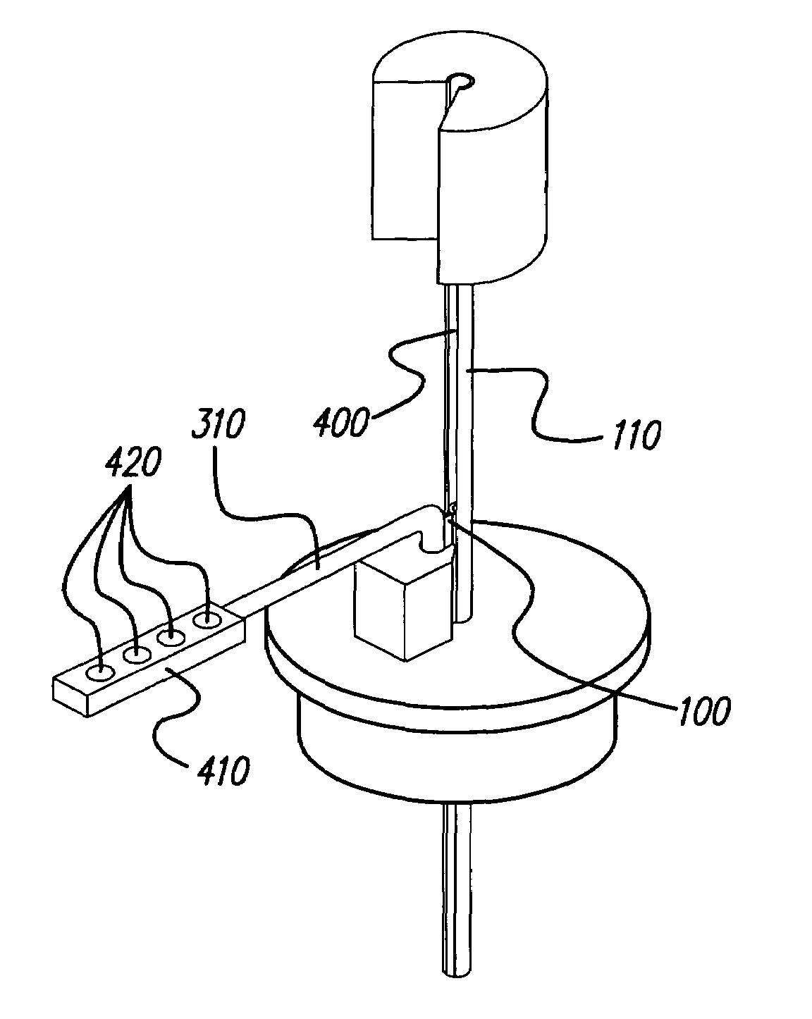
[0016]Conventionally, when a cannula enveloping a lead is removed from a stereotactic frame, the cannula is pulled upward, away from the brain, as it slides like a sleeve off of the lead. Before the distal tip of the cannula exits the skull, the proximal tip of the cannula has covered the proximal end of the lead. Thus, as the proximal length of the lead is cloaked by the cannula and the distal length of the lead is cloaked by the skull, dura mater, and brain, no portion of the lead is visible to the surgeon. Yet in order to insure that the lead does not move during removal of the cannula and other structures, e.g., the recording microelectrode, it is critical that at least a portion of the lead be seen by the surgeon at all times, and if possible, locked into place. The present systems and methods avoid lead displacement by permitting a surgeon to view and lock the lead into place at all times during the removal of a cannula and other structures such as the recording microelectrode.
[0017]The present systems and methods allow a surgeon to remove a recording microelectrode before or after a cannula is removed. The present systems and methods also allow a surgeon to place a non-isodiametric lead within a cannula lumen. Further, the present systems and methods prevent fluid ingress into the connector end of a lead. Further still, the present systems and methods allow a surgeon to deliver continuous stimulation and receive continuous recording signals through the lad during removal of the surgical insertion tools (i.e., the cannula, recording microelectrode, and other devices) in order to continuously monitor any potential changes in stimulation efficacy of the lead during removal of the insertion tools.

Problems solved by technology

Each time an object is inserted into the brain there is approximately a 5% risk of hemorrhage.
Creating multiple tracts increases the risk for intracranial bleeding, duration of operation, post-operative infection, and operative risk.
Creating new tracts is fraught with misalignment / misplacement problems because the introduction cannulas may not trace the exact pathways desired.

Method used


Image

  • System and method for insertion of a device into the brain
  • System and method for insertion of a device into the brain
  • System and method for insertion of a device into the brain

Examples


Embodiment Construction

[0027]The following description includes the best mode presently contemplated for carrying out the present systems and methods. This description is not to be taken in a limiting sense, but is made merely for the purpose of describing the general principles of the present systems and methods. The scope of the invention should be determined with reference to the claims.

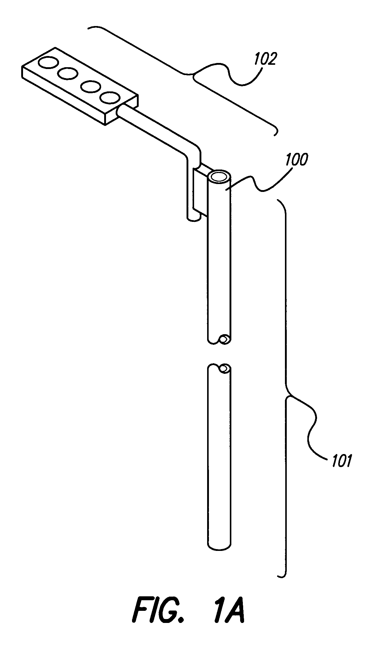
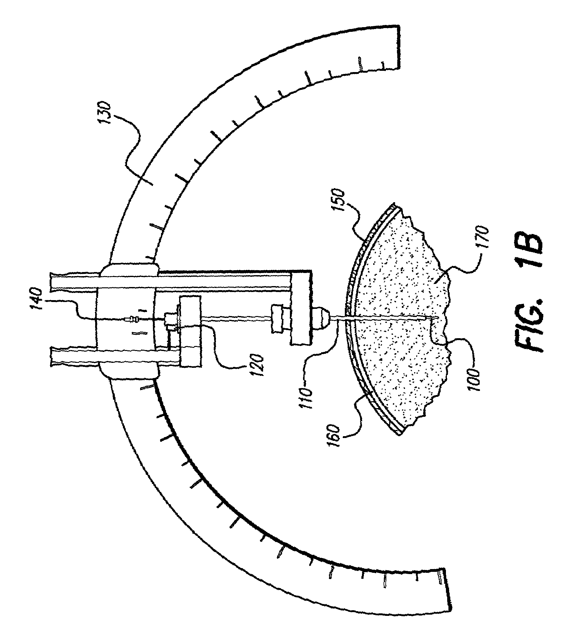
[0028]The systems and methods described herein that allow for visualization and locking of a deep brain stimulation (DBS) lead, or other elongated medical structure, during a surgical tool removal process of a DBS procedure, hence eliminating the risk of lead movement. Visualization and locking of the lead during the surgical removal process can be accomplished using a unique lead system.

[0029]For this disclosure, the lead system refers to (1) a lead, (2) a slit cannula, (3) a lead lock, and (4) a recording microelectrode or stylet. The lead may have a lumen for receiving the recording microelectrode. The lead is also d...


PUM


Abstract

A deep brain stimulation lead system has a medical lead, or similar elongate medical insertion device, securable with a lead lock through a cannula slit, thereby allowing a lead to remain electrically operative and preventing movement of the lead during removal of a stylet, recording microelectrode, or cannula.

Description

[0001]The present application claims the benefit of U.S. Provisional Patent Application Ser. No. 60 / 404,692, filed Aug. 20, 2002, which application is incorporated herein by reference in its entirety.FIELD OF THE INVENTION[0002]The present invention relates to systems and methods for inserting a medical device into the brain for deep brain stimulation.BACKGROUND OF THE INVENTION[0003]Deep brain stimulation (DBS) and other related procedures involving implantation of leads and catheters are increasingly used to treat Parkinson's disease, dystonia, essential tremor, seizure disorders, obesity, depression, restoration of motor control, and other debilitating diseases. During these procedures, a catheter, lead, or other medical device is strategically placed at a target site in the brain. Locating the “best” target for stimulation in the brain can be a painstaking procedure.[0004]Implantation of a lead for DBS generally involves the following preliminary steps: (a) anatomical mapping an...

Claims


Application Information

Patent Timeline
Patent Type & Authority Patents(United States)
IPC IPC(8): A61N1/18
CPCA61N1/0534A61N1/0539A61B19/201A61B90/11
Inventor PIANCA, ANNE MKUZMA, JANUSZ A
Owner BOSTON SCI NEUROMODULATION CORP
Learn More